Magnetic-bearing motor

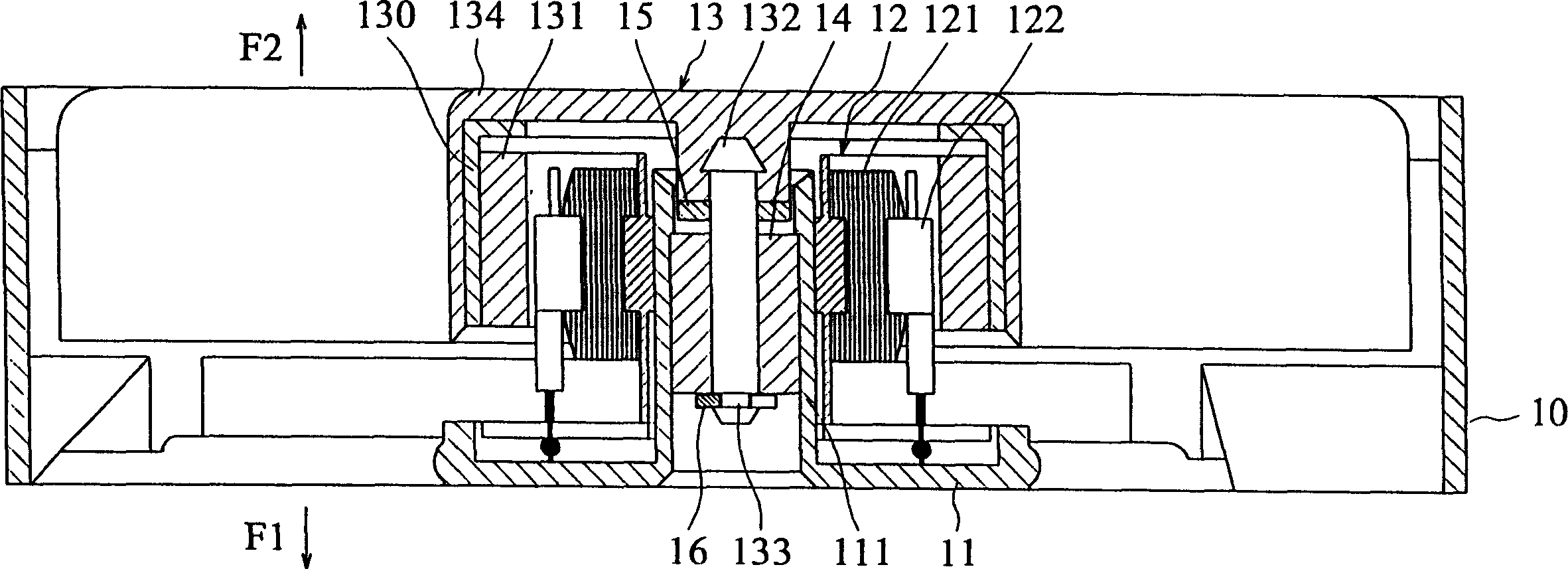
A magnetic bearing and motor technology, applied in the field of motors, can solve the problems of high heat, shortened service life, and offset of the rotating shaft 132 of the C-shaped buckle, and achieve good rotation stability.

Inactive Publication Date: 2005-01-19
DELTA ELECTRONICS INC
View PDF0 Cites 0 Cited by
  • Summary
  • Abstract
  • Description
  • Claims
  • Application Information

AI Technical Summary

Problems solved by technology

[0006] 1. When the fan rotates, the wear and friction between the C-shaped retaining ring 16 and the bearing 14 will generate high heat, resulting in a shortened service life
[0007] 2. The friction between the C-shape buckle 16 and the bearing 14 produces noise, or the rotation speed is unstable due to different degrees of friction
[0008] 3. There is a magnetic deviation between the rotor 13 and the stator 12. When the rotor 13 rotates, a magnetic levitation phenomenon will occur, so that the two will generate a magnetic balance at a fixed position. In this way, the rotor 13 and the stator 12 are not in the original equilibrium position when rotating, but produce another new equilibrium position according to the magnitude of the external force. This situation will cause considerable problems in design.

Method used


Image

  • Magnetic-bearing motor
  • Magnetic-bearing motor
  • Magnetic-bearing motor

Examples


Embodiment Construction

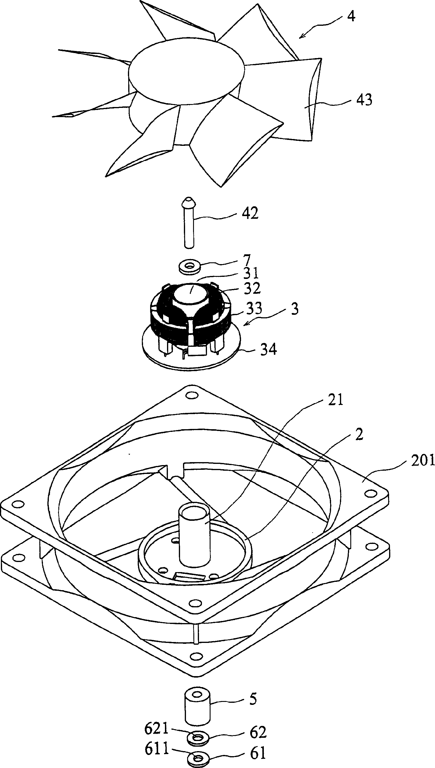
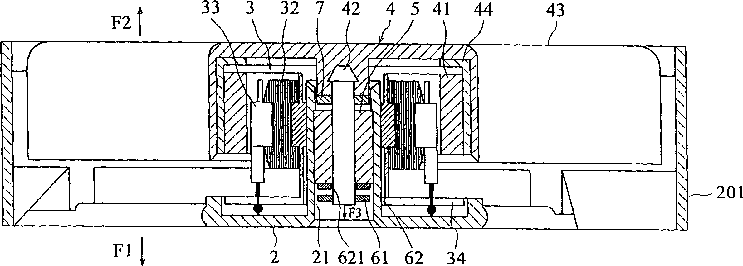
[0045] see figure 2 , 3 As the first preferred embodiment of the present invention, the magnetic bearing motor of the present invention includes: a base 2, a stator 3, a rotor 4, a bearing 5, a magnetic element group, and an elastic washer 7, wherein:

[0046] The base 2 is located at the center of a fan frame 201 , and the two are combined into one body. A bearing seat 21 is arranged at the center of the base 2 .

[0047] The center of the stator 3 is provided with a socket 31, and the periphery of the socket 31 is provided with a coil 32 and a silicon steel sheet 33, and a circuit board 34 is provided below, and the coil 32, the silicon steel sheet 33, and the circuit board 34 are electrically connected. , the sleeve portion 31 fits and is fixed outside the bearing seat 21 of the base 2 .

[0048] The rotor 4 is provided with a hollow cylindrical body 44 with an open end, its outer peripheral wall is combined with a fan blade 43, its inner peripheral wall is provided with...


PUM


Abstract

The motor includes a support with pedestal, a stator fixed on the pedestal, a rotor with a shaft and being rotated on the exciting magnetic force, a bearing fixed on the pedestal to support the shaft, and a magnetic element combination including the first element fixed on the shaft and the second one fixed on the pedestal for the shaft on penetrate, with the first and the second elements producing magnetic forces. The present invention can position the shaft axially to avoid contact friction during rotation.

Description

【Technical field】 [0001] The invention relates to a motor, in particular to a magnetic bearing motor which avoids rotational friction. 【Background technique】 [0002] Most of the motor structures used today use heat-resistant gaskets or metal C-shaped buckles as the positioning of the shaft. Please refer to figure 1 , is a known self-lubricating bearing fan motor structure, which includes a base 11, a stator 12, a rotor 13, a bearing 14, an elastic washer 15, and a C-shaped buckle 16; wherein: [0003] The base 11 is located at the center of a fan frame 10, and the two are combined into one body. The center of the base 11 is provided with a bearing seat 111; the stator 12 is fitted outside the bearing 111 and fixed with the base 11. It is provided with Coil 121 and silicon steel sheet 122; the bearing 14 is a self-lubricating bearing set and fixed on the bearing seat 111 of the base 11; the rotor 13 is provided with a hollow cylindrical body 130 with an open end, and its ou...

Claims


Application Information

Patent Timeline
Patent Type & Authority Patents(China)
IPC IPC(8): H02K7/09
Inventor 黄文喜林国正庄德财蔡明熹
Owner DELTA ELECTRONICS INC
Why Eureka
Try Eureka