
Magnetic levitation driver with 5DOF light-path control

A drive and magnetic levitation technology, applied in the laser field, can solve problems such as difficult to achieve multiple degrees of freedom, increased weight, and large inertia of the laser cutting head

Pending Publication Date: 2020-12-25
SHENYANG POLYTECHNIC UNIV
View PDF0 Cites 0 Cited by
  • Summary
  • Abstract
  • Description
  • Claims
  • Application Information

AI Technical Summary

Problems solved by technology

[0003] Using traditional hydraulic and mechanical structures, it is difficult to achieve multiple degrees of freedom
The traditional structure will increase the size and weight of the laser head, resulting in large inertia and slow response during the movement of the laser cutting head, which cannot meet the needs of high-speed and high-precision processing

Method used


Image

  • Magnetic levitation driver with 5DOF light-path control
  • Magnetic levitation driver with 5DOF light-path control
  • Magnetic levitation driver with 5DOF light-path control

Examples


Embodiment Construction

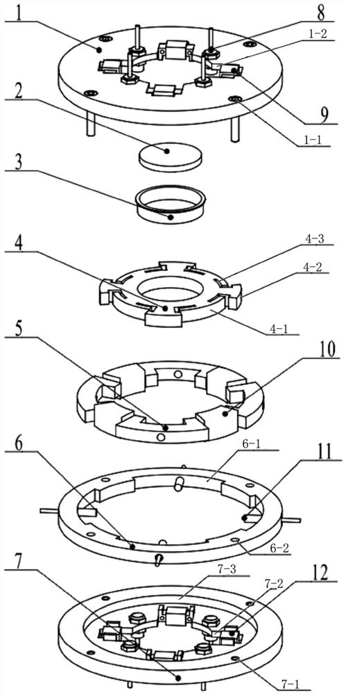
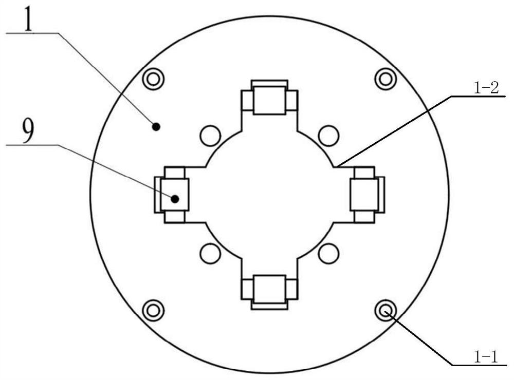
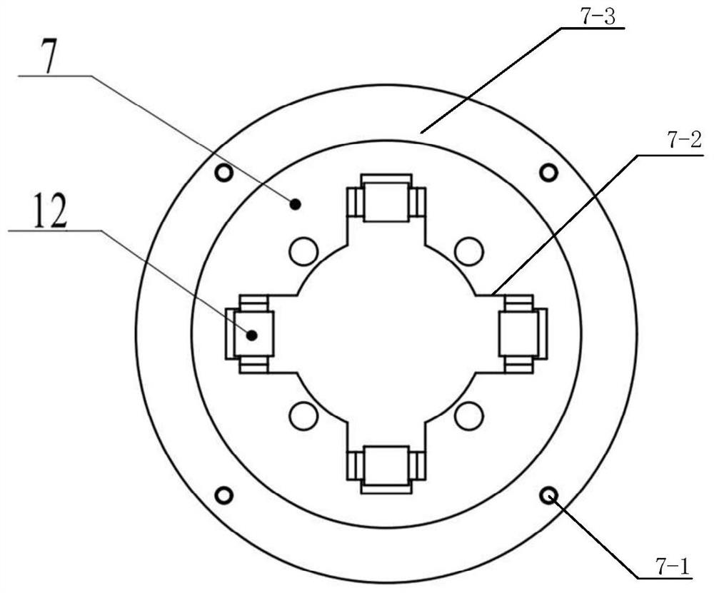
[0034] A 5DOF optical path control magnetic levitation driver, the driver includes an upper end cover 1, a float 4, a radial stator 5, a connecting ring 6 and a lower end cover 7; the float 4 is located in the radial stator 5, and a gap is left between the float 4 and the radial stator Air gap (the air gap here is the distance between the float and the radial stator coil. There is an air gap margin in the design to avoid the problem of out-of-control adsorption caused by too small air gap when the float moves in the x and y directions. There is also an air gap between the float and the axial stator coil), the radial stator 5 is installed in the connecting ring 6, and the upper end cover 1 and the lower end cover 7 are distributed on both sides of the connecting ring 6 (the connecting ring 6 is placed on the upper end cover 1 and the lower end cover 7);

[0035] Radial coils 10 are installed on the radial stator 5, and the radial coils 10 are at least four groups of even groups...


PUM


Abstract

The invention discloses a magnetic levitation driver with 5DOF light-path control. The driver comprises an upper end cover 1, a floater 4, a radial stator 5, a connecting ring 6 and a lower end cover7, wherein the floater 4 is positioned in the radial stator 5, and an air gap is reserved between the floater 4 and the radial stator; the radial stator 5 is arranged in the connecting ring 6; and theupper end cover 1 and the lower end cover 7 are distributed on the two sides of the connecting ring 6. The magnetic levitation driver with 5DOF light-path control provided by the embodiment of the invention can realize five-degree-of-freedom motion control, is compact in structure, and has the characteristics of high response speed and high precision.

Description

technical field [0001] The invention relates to the field of laser technology, in particular to a 5DOF optical path control magnetic levitation driver. Background technique [0002] During the laser cutting process, by controlling the position of the focusing lens in the laser optical path, and then controlling the position of the focus of the laser beam relative to the central axis of the auxiliary gas, the off-axis laser cutting process method. Under the same processing conditions, the processing efficiency of the laser cutting machine and the processing quality of the slit can be effectively improved. During the processing of the off-axis laser cutting method, it is necessary to control the axis of the laser beam and the center of the nozzle in real time to ensure a specific relationship in the feed direction. Therefore, there is a need for a micro-actuator capable of high response speed, high precision and easy control. [0003] Using traditional hydraulic and mechanic...

Claims


Application Information

Patent Timeline
Patent Type & Authority Applications(China)
IPC IPC(8): B23K26/38B23K26/04H02N15/00
CPCB23K26/38B23K26/04H02N15/00
Inventor 孙凤赵川金俊杰徐方超李强王韬宇
Owner SHENYANG POLYTECHNIC UNIV
Learn More