Magnetic energy power machine

An energy and power technology, applied in the direction of generators/motors, electrical components, etc., can solve the problems of low efficiency of magnetic power machines, and achieve the effects of high utilization rate of magnetic energy, convenient transmission, and energy saving.

Inactive Publication Date: 2013-09-18
章建成
View PDF1 Cites 0 Cited by
  • Summary
  • Abstract
  • Description
  • Claims
  • Application Information

AI Technical Summary

Problems solved by technology

[0004] The technical problem to be solved by the present invention is to overcome the defect of low efficiency of the magnetic energy power machine in the prior art, and provide a magnetic power machine with magnetic energy The magnetic energy utilization rate of the power machine is high, which can save or even replace the power machine equipment using other energy sources

Method used


Image

  • Magnetic energy power machine
  • Magnetic energy power machine
  • Magnetic energy power machine

Examples


Embodiment 1

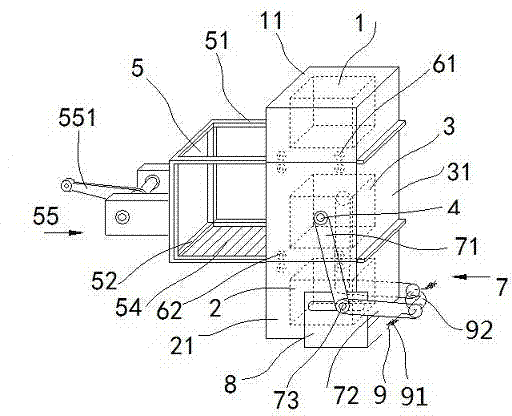
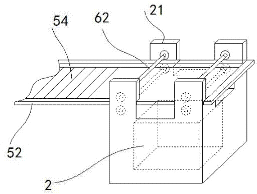
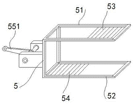
[0032] Embodiment 1: as figure 1As shown, a magnetic power machine includes a frame, a fixed magnet 1, a fixed magnet 2 2, a moving magnet 3 and a stirring magnet plate. The fixed magnet 1 and the fixed magnet 2 have the same structure, and the fixed magnet 1 is fixedly connected with a lower end. The first protective cover 11 is an opening, the fixed magnet 2 2 is fixedly connected with a protective cover 21 whose upper end is open, and the outer side of the moving magnet 3 is fixed with a protective cover 31 whose upper and lower ends are open; the fixed magnet 1 passes through the protective cover 1. 11 is fixed on the upper end of the frame, the fixed magnet 2 2 is fixed on the lower end of the frame at the corresponding part of the fixed magnet 1 1 through the protective cover 2 21, and the moving magnet 3 can be slid up and down on the fixed magnet 1 and the fixed magnet 2 2. In the neutral position in the middle, the distance of the neutral position is larger than th...

Embodiment 2

[0043] Embodiment 2: The transmission mechanism of the output power includes two connecting rods arranged symmetrically on the left and right, and the upper ends of the two connecting rods are respectively connected with the circular shaft 1 fixed on the right side of the third protective cover and the circular shaft 2 on the left side of the protective cover 3. The lower ends of the two connecting rods are connected with the two ends of the crankshaft arranged at the lower part of the frame respectively, and the axis of the first round shaft, the axis of the second round shaft, the axis of the moving magnet and the axis of the crankshaft are in the same plane; The moving magnet of this structure can be compared to the piston of an internal combustion engine. The internal combustion engine relies on the piston to push the crankshaft through the connecting rod to do work, while the present invention relies on the moving magnet to push the crankshaft through the connecting rod...

Embodiment 3

[0044] Example 3: The upper end face of the protective cover 1 has a through hole, the lower end surface of the protective cover 2 has a through hole, and the fixed magnetization 1 passes through the through hole on the upper end face of the protective cover 1, the frame, the upper frame of the stirring magnet plate frame, and the stirring magnet. The plate 1 and the fixed magnet 1 establish the upper magnetic circuit; the fixed magnet 2 establishes the lower magnetic circuit through the through hole on the lower end surface of the protective cover 2, the frame, the lower frame of the stirring magnet plate frame, the stirring magnet plate 2 and the fixed magnet 2, and the rest of the structure Same as Example 1.


PUM


Abstract

The invention discloses a magnetic energy power machine. The magnetic energy power machine comprises a machine frame, two fixed magnets, a moveable magnet and magnetism stirring iron plates, wherein the fixed magnet I and the fixed magnet II are fixedly connected with a protecting cover I and a protecting cover II; the moveable magnet is fixedly connected with a protecting cover III of which the upper end and the lower end are opened; the protecting cover I and the protecting cover II are fixedly connected to the upper end and the lower end of the machine frame; the moveable magnet is glidingly matched at a neutral position between the fixed magnet I and the fixed magnet II; the distance of the neutral position is larger than the height of the moveable magnet by a certain value; the same poles of the fixed magnet I and the moveable magnet are opposite; the same poles of the moveable magnet and the fixed magnet II are opposite; a magnetism stirring iron plate frame with an upper side frame and a lower side frame is arranged on one side of the machine frame; the magnetism stirring iron plate I is fixedly arranged at the right end of the upper side frame; the magnetism stirring iron plate II is fixedly arranged at the left end of the lower side frame; a rolling shaft group I is arranged at the lower end of the protecting cover I and clamps the upper side frame; a rolling shaft group II is arranged at the lower end of the protecting cover II and clamps the lower side frame; the left ends of the magnetism stirring iron plates are connected with a reciprocating mechanism and a motor; and the moveable magnet is connected with an output transmission mechanism through a round shaft I and a round shaft II connected to the left side and the right side of a protecting cover III. The magnetic energy power machine has the advantages that energy resources are saved, and labor-saving significance is great due to the fact that the rolling shaft group I and the rolling shaft group II are arranged.

Description

technical field [0001] The invention belongs to the technical field of magnetic energy machinery, and in particular relates to a device for converting magnetic energy into mechanical energy and outputting it through the up and down reciprocating motion of a moving magnet. Background technique [0002] The magnetic drive is to form a certain magnetic field between the two components of the device, and the repulsive force and attractive force of the magnetic field make the two components move relative to each other. The advantage of magnetic actuation is that it avoids the use of leads, which are unavoidable in electrostatic, thermal, and piezoelectric drives. The usual magnetic drive is mostly completed by combining energy provided by an alternating magnetic field and a magnetic stirrer. If permanent strong magnetism is applied, the excitation device can be avoided. In addition to the characteristics of natural magnets, man-made permanent strong magnetism also has the charac...

Claims


Application Information

Patent Timeline
Patent Type & Authority Applications(China)
IPC IPC(8): H02N11/00
Inventor 章建成
Owner 章建成
Why Eureka
Try Eureka