
Energy accumulation magnetically-actuated method and energy accumulation magnetic driving motor

A magnetic drive and magnetic motor technology, applied in the electromagnetic field, can solve the problems that the energy storage density cannot meet the growing needs of people, it is difficult to popularize and apply, and the structure is unreasonable.

Inactive Publication Date: 2008-12-10
吴光进
View PDF0 Cites 1 Cited by
  • Summary
  • Abstract
  • Description
  • Claims
  • Application Information

AI Technical Summary

Problems solved by technology

Before the present invention, in order to seek new energy sources, people used the mutual attraction and repulsion of permanent magnets as the driving force to design magnetic motors, and used the principle of permanent magnets to repel each other and attract each other to design rotors, electromagnetic pulse kinetic energy, etc. The common point of the design is that both the stator and the rotor use the attraction and repulsion of the permanent magnet as the power; the above-mentioned magnetic motor has a certain positive significance for solving the energy problem, but the above-mentioned invention obviously has the interference of the force of the two sexes, and the structure is unreasonable, etc. , so it is difficult to promote the application
[0003] Existing energy storage devices such as lead-acid batteries require heavy metals, sulfuric acid and other substances that pose a serious threat to the environment during their manufacture and use, and their energy storage density cannot meet the growing needs of people.
[0004] In the prior art, no technical solution has been found to directly realize energy storage and power output by using a set of mechanisms or devices

Method used


Image

  • Energy accumulation magnetically-actuated method and energy accumulation magnetic driving motor
  • Energy accumulation magnetically-actuated method and energy accumulation magnetic driving motor
  • Energy accumulation magnetically-actuated method and energy accumulation magnetic driving motor

Examples


Embodiment 1

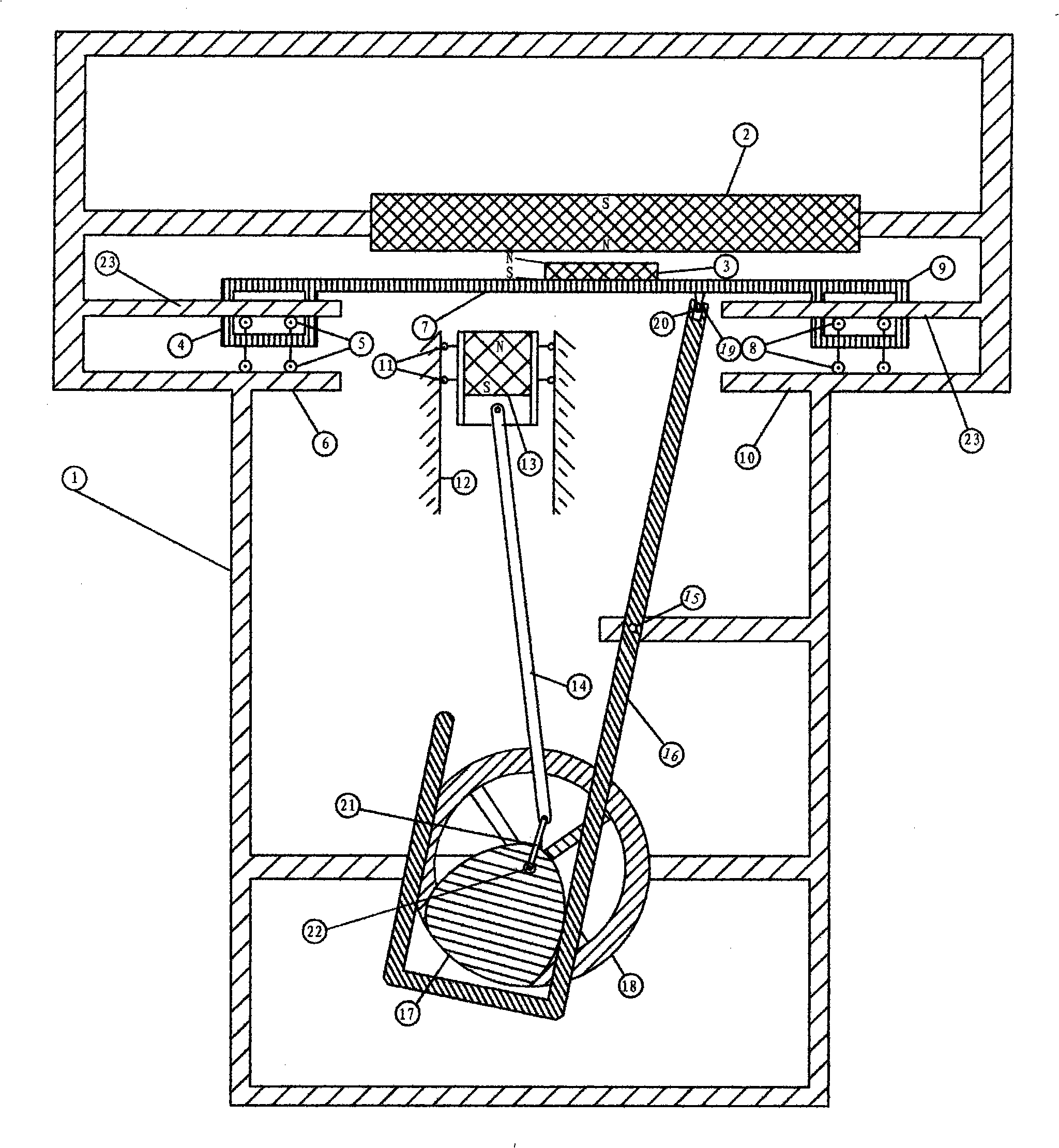
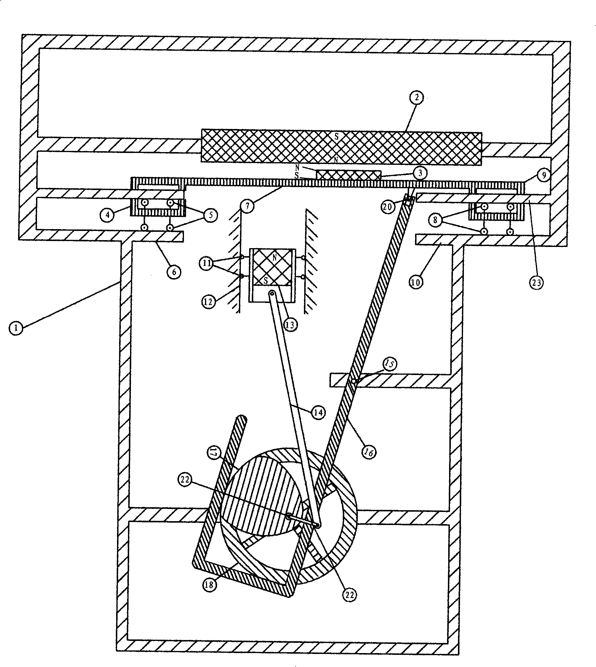
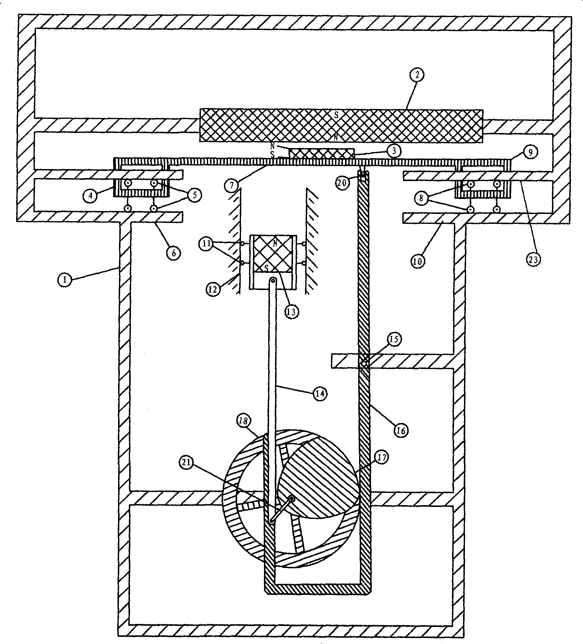
[0041] Example 1: see Figure 1 ~ Figure 4 , The energy storage magnetic drive method provided in this embodiment includes the following steps:

[0042] 1) A stationary magnet 2 made of permanent magnet material that stores magnetic energy is set on the frame 1;

[0043] 2) A magnet piston 13 of opposite polarity and its channel 12 are arranged directly below the fixed magnet 2 and within the range of its magnetic field, forming a repulsive magnetic field between the two; under the action of the magnetic field, The magnet piston 13 descends along its channel 12;

[0044] 3) In or near the repulsive magnetic field between the stationary magnet 2 and the magnet piston 13, a moving magnet 3 is provided for changing the repulsive magnetic field and blocking the effect of the original magnetic field. In the initial state, the moving magnet 3 The polarity of the upper magnetic field is the same as that of the stationary magnet 2, and the polarity of the lower magnetic field is opposite t...

Embodiment 2

[0061] Embodiment 2: This embodiment provides an energy storage magnetic drive method, the basic steps are the same as the embodiment, and the difference lies in:

[0062] In the step 3), the moving magnet 3 is an electromagnetic winding made of a coil, which is set in the repulsive magnetic field between the fixed magnet 2 and the magnet piston 13, and a corresponding control circuit is set. And trigger point;

[0063] The step 5) is to restore the magnetic field polarity of the moving magnet 2 made of the electromagnetic winding, causing the repulsive magnetic field to change as follows: the upper part and the stationary magnet 2 form an attractive magnetic field, and the lower part and The magnet piston 13 forms a repulsive magnetic field, and under the action of the magnetic field, causes the magnet piston 13 to descend along its channel 12;

[0064] The step 7) is to set up a crank mechanism connected to the magnet piston 13 and the moving magnet 2. One end of the crank mecha...


PUM


Abstract

The invention discloses an energy storage magnetic force driving method, characterized by including: 1) setting a stable magnet stored with magnetic energy made of permanent magnet materials; 2) setting a magnet piston with opposite polarity, wherein the stable magnet drives the piston to descend; 3) setting a movable magnet causing the repulsive magnetic field to change and obstruct the original magnetic field; 4) causing the movable magnet to move into the inside of the repulsive magnetic field or changing the polarity of the magnetic field, causing the repulsive magnetic field to change, driving the magnet piston to go upward; 5) causing the movable magnet to move to the outside of the repulsive magnetic field or recover the polarity of the magnetic field, driving the magnet piston to go downward; 6) repeating the steps 4)-5), under the action of the alternating magnetic field, causing the magnet piston to repeat the circulating motion of descending and ascending, to convert the magnetic energy into the mechanical energy. The invention also discloses an energy storage magnetic motor for realizing thereof, which has the advantages of simple structure, no noise, large moment, high magnetic energy availability and environmental protection and the like.

Description

Technical field [0001] The invention relates to the field of electromagnetic technology, in particular to a magnetic drive method and an energy storage magnetic motive using energy storage materials and a variable magnetic field. Background technique [0002] Existing various motive power engines such as gasoline engines, diesel engines, and fuel steam engines have been used in many areas of society. Some equipment has huge investment, some consumes high fuel costs, and waste emissions, noise, etc., have serious environmental pollution. Because the energy used by the above engines is non-renewable resources such as coal, oil, etc., due to limited resources, energy consumption is more and more valued by people. In order to overcome the energy crisis, countries around the world have invested a lot of manpower and material resources in research and development of new energy. Before the present invention, in order to seek new energy, people used the mutual attraction and repulsion of...

Claims


Application Information

Patent Timeline
Patent Type & Authority Applications(China)
IPC IPC(8): H02N11/00
Inventor 吴先进
Owner 吴光进
Learn More