Stator core forming method

A stator core and forming method technology, which is applied in the manufacture of stator/rotor bodies, motor generators, electrical components, etc., can solve the problems of low utilization rate of copper wires, reduction of assembly inner holes, etc., and achieve increased assembly inner holes, The effect of improving copper wire utilization

Active Publication Date: 2019-04-16
ZHEJIANG PANGOOD POWER TECH CO LTD
View PDF5 Cites 1 Cited by
  • Summary
  • Abstract
  • Description
  • Claims
  • Application Information

AI Technical Summary

Problems solved by technology

In order to avoid the sharp corner here, it is necessary to use a longer end of the coil, resulti

Method used


Image

  • Stator core forming method
  • Stator core forming method
  • Stator core forming method

Examples


Embodiment 1

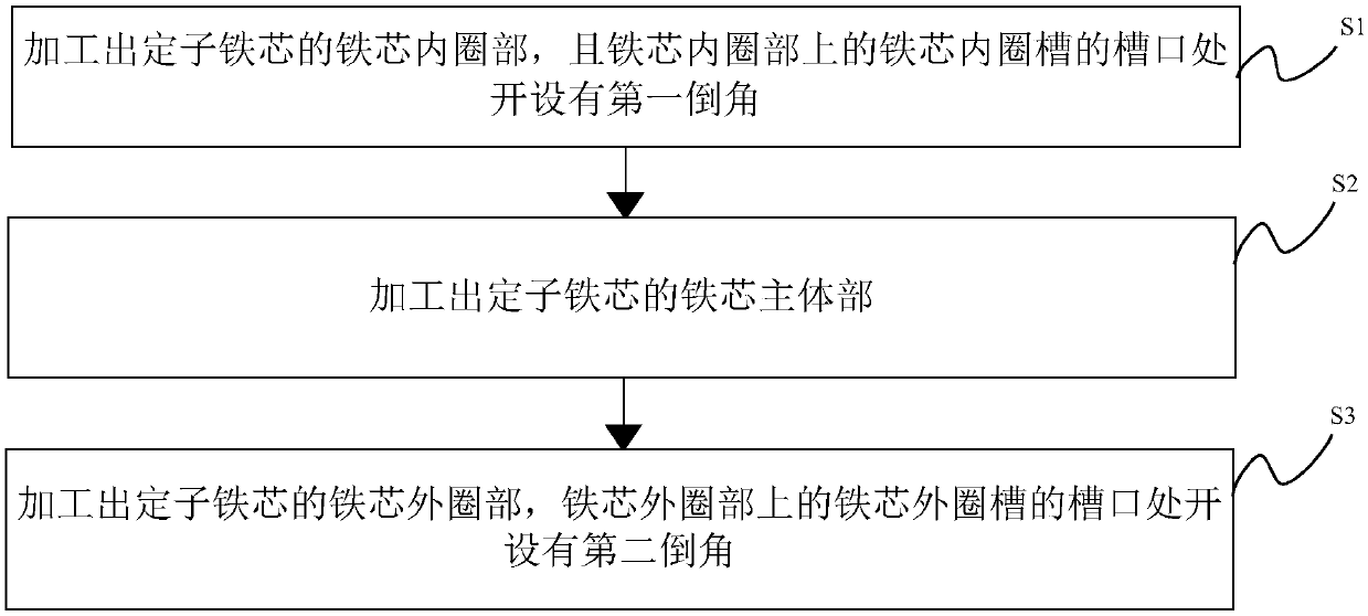
[0043] see Figure 1-5 , is a flow chart of the stator core forming method provided by the present invention.

[0044] The invention discloses a stator core forming method, comprising the following steps:

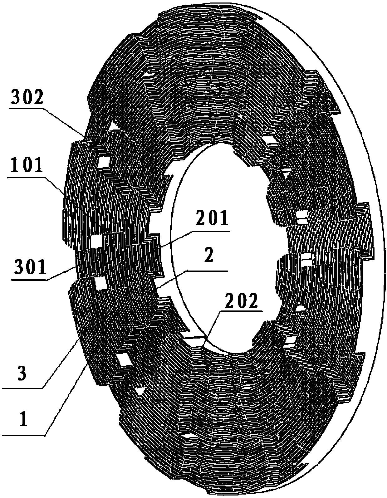
[0045] Step S1 : Process the inner core ring part 2 of the stator core, and a first chamfer 202 is provided at the opening of the inner ring groove 201 on the inner ring part 2 of the iron core.

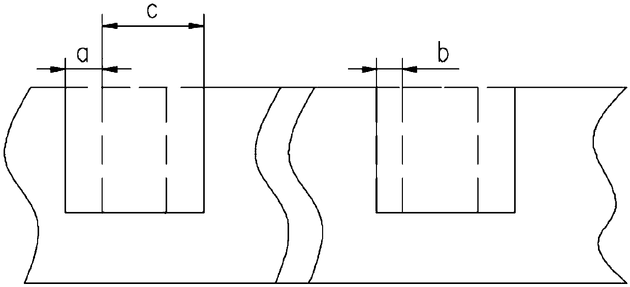
[0046] The inner ring portion 2 of the iron core can be formed by die pressing, or by stamping and rolling of a silicon steel sheet. A plurality of iron core inner ring slots 201 are opened on the processed iron core inner ring portion 2 along the radial direction of the iron core inner ring portion 2 .

[0047] The slots 201 of the inner ring of the iron core are evenly distributed on the inner ring portion 2 of the iron core.

[0048] The first chamfer 202 is provided at the notch at the end of the iron core inner ring groove 201 close to its axis. The first chamfer 202 may ...

Embodiment 2

[0059]In yet another embodiment of the present invention, the stator core forming method in this embodiment is similar to the stator core forming method in the first embodiment, and the similarities will not be repeated, and only the differences will be introduced.

[0060] In this embodiment, the present invention specifically discloses that the stator core is integrally formed by punching and rolling silicon steel sheets.

[0061] Wherein, processing the inner ring portion 2 of the iron core specifically includes the following steps:

[0062] S11: According to the thickness of the silicon steel sheet, combined with the groove width of the inner ring groove 201 of the iron core and the size of the first chamfer 202, calculate the first feeding amount of the silicon steel sheet when punching dies with different turns.

[0063] The first chamfer 202 may be a rounded corner or a chamfer of other shapes.

[0064] S12: Die the silicon steel sheet according to the calculated first...

Embodiment 3

[0095] In the third embodiment of the present invention, the stator core forming method in this embodiment is similar to the stator core forming method in the first embodiment, and the similarities will not be repeated, and only the differences will be introduced.

[0096] In this embodiment, it is disclosed that the inner ring portion 2 of the processed iron core includes:

[0097] S13: The main body of the inner ring of the iron core is made by molding, and the inner ring groove 201 of the iron core is opened on the main body of the inner ring of the iron core.

[0098] The molded material is specifically a soft magnetic material, and it should be noted that it may also be other magnetic materials.

[0099] S14: A first chamfer 202 is provided at the notch of the core inner ring groove 201 of the iron core inner ring main body to form the iron core inner ring part 2 .

[0100] The first chamfer 202 may be a rounded corner or a chamfer of other shapes.

[0101] Further, the...


PUM

PropertyMeasurementUnit
Thicknessaaaaaaaaaa

Abstract

The invention discloses a stator core forming method. The method comprises a step of processing an iron core inner ring part of a stator core, wherein a first chamfer is set at a notch of an iron coreinner ring groove on the iron core inner ring part, a step of processing an iron core main body part of the stator iron core, wherein the iron core main body part sleeves the iron core inner ring part, and a step of processing an iron core outer ring part of the stator core, wherein the iron core outer ring part sleeves the iron core main body part, and a second chamfer is set at a notch of an iron core outer ring groove on the iron core outer ring part. According to the invention, the iron core inner ring part of the stator core, the iron core main body part of the stator iron core and the iron core outer ring part are orderly processed, a stator groove is formed by the iron core outer ring groove, the iron core inner ring groove, the iron core inner ring groove and an iron core main body groove, the first chamfer is set at the notch of the iron core inner ring groove, the second chamfer is set at the notch of the iron core outer ring groove, the avoidance of a sharp corner at that place is not needed, long end parts are not required by coils at the notches of the iron core inner ring groove and the iron core outer ring groove, therefore, assembly inner holes are increased, and the utilization of a copper wire is improved.

Description

technical field [0001] The invention relates to the technical field of motors, in particular to a stator core forming method. Background technique [0002] The stator core of the axial field motor has a certain number of stator slots along the radial direction on its end face, which are used to embed copper wires for conduction. [0003] Currently, if figure 1 As shown, the stator slot 1' of the stator core is usually a straight-line through slot, and the slots of the inner and outer rings of the stator slot 1' are sharp corners. In order to avoid the sharp corner here, it is necessary to use a longer end of the coil, resulting in a reduction in the inner hole of the assembly and a low utilization rate of the copper wire. [0004] Therefore, how to improve the utilization rate of the copper wires when the stator core is wound is a technical problem to be solved urgently by those skilled in the art. Contents of the invention [0005] In view of this, the object of the pr...

Claims


Application Information

Patent Timeline
IPC IPC(8): H02K15/02
CPCH02K15/024
Inventor 吴星叶宁
Owner ZHEJIANG PANGOOD POWER TECH CO LTD
Why Eureka
Try Eureka