Electric permanent magnetic coupler

An electro-permanent magnet and coupler technology, applied in the direction of electrical components, electromechanical devices, electric components, etc., can solve problems such as infringement, complicated mechanism, mineral heat accumulation, etc., and achieve high utilization rate of magnetic energy, short production cycle, and heat generation. small effect

Inactive Publication Date: 2015-08-12
YANGZHOU UNION TRANSMISSION TECH
View PDF0 Cites 1 Cited by
  • Summary
  • Abstract
  • Description
  • Claims
  • Application Information

AI Technical Summary

Problems solved by technology

However, there are still some defects and deficiencies in its design, such as: the air-cooled heat dissipation design is not advanced; the permanent magnetic coupler takes up axial space, and the motor needs to be moved back, which brings about re-construction of the installation foundation. Cannot be applied; the air gap adjustment mechanism, propulsion mechanism, bearing shafting and electric actuator are complicated and have a high failure rate; the daily inspection and regular maintenance requirements are high; the speed regulation range is narrow; the magnetic eddy current occurrence rate and utilization rate are low, and the thermal efficiency High; the water-cooled cooling system is cumbersome, and the cooling water has damage to the equipment and mineral heat accumulation

Method used


Image

  • Electric permanent magnetic coupler
  • Electric permanent magnetic coupler
  • Electric permanent magnetic coupler

Examples


Embodiment Construction

[0031] The present invention is specifically described below in conjunction with accompanying drawing:

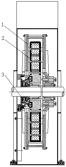
[0032] The electro-permanent magnet coupler of the present invention is composed of a conductor rotor 1, an electro-permanent magnet rotor 2, a retractable electrode mechanism 3, an expansion sleeve, an electro-permanent magnet controller and a volute-type wind cover, wherein the electro-permanent magnet controller and the volute-type wind cover The cover is an existing mature industrial product and technology, and the expansion sleeve is an optional product based on the site situation.

[0033] In the electro-permanent magnet coupler of the present invention, the conductor rotor 1 and the electro-permanent magnet rotor 2 are respectively socketed on the motor main shaft and the load main shaft by using expansion sleeves, and the conductor rotor 1 wraps the radial surface and the circumferential surface of the electro-permanent magnet rotor 2, are in a non-contact state.

...


PUM


Abstract

The invention relates to an electric permanent magnetic coupler. The electric permanent magnetic coupler is composed of a conductor rotor, an electric permanent magnetic rotor and a telescoping electrode mechanism. The conductor rotor wraps the radial face and the circumferential surface, the conductor rotor is formed in a way that a high-permeability layer is attached to a high-conductivity layer, the high-conductivity layer faces the electric permanent magnetic rotor, and the high-permeability layer is arranged outside the high-conductivity layer; the electric permanent magnetic rotor comprises a diamagnetic substrate, the diamagnetic substrate is provided with a high-coercivity main permanent magnet and a low-coercivity electric permanent magnet which are arranged at an interval, and the main permanent magnet is connected with the electric permanent magnet through a magnetizer; the electric permanent magnet is wrapped by a magnetizing coil, and two ends of the magnetizing coil are respectively connected with two conducting rings; and the telescoping electrode mechanism comprises an electromagnetic system and a contact system which is contacted with the conducting rings. The electric permanent magnetic coupler is convenient to process, assemble, transport and install, and a motor does not need to be moved backwards.

Description

technical field [0001] The invention relates to the technical field of transmission shaft coupling drive, the technical field of load speed regulation and the field of power drag, in particular to an electro-permanent magnetic coupler capable of controllably adjusting the transmission of magnetic coupling torque. Background technique [0002] In today's society, in various industrial occasions and people's production and life, the fields involving drive shaft drive and speed regulation are very extensive, and the common ones are motors, internal combustion engines, and steam turbines. Due to the wide range of application fields, the corresponding technologies are also very complicated. [0003] Energy conservation and consumption reduction has always been one of the key concerns of the world. my country has also listed the energy conservation of motor systems as one of the top ten key energy conservation projects in the "Medium and Long-term Special Plan for Energy Conservat...

Claims


Application Information

Patent Timeline
Patent Type & Authority Applications(China)
IPC IPC(8): H02K51/00
Inventor 蒯长进沈力
Owner YANGZHOU UNION TRANSMISSION TECH
Why Eureka
Try Eureka