a magnetic separator

A magnetic separator and magnetic separation technology, applied in the field of magnetic separators, can solve the problems that the magnetic energy of the magnetic system cannot be fully utilized, the magnetic field strength of the outer wall of the drum is weakened, and the physical inclusions of the magnetic separation concentrate are large, so as to improve the utilization rate of magnetic energy, The effect of small footprint and wide magnetic separation area

Active Publication Date: 2015-12-23
CHANGSHA RES INST OF MINING & METALLURGY
View PDF7 Cites 1 Cited by
  • Summary
  • Abstract
  • Description
  • Claims
  • Application Information

AI Technical Summary

Problems solved by technology

[0004] At present, the magnetic separators used to process magnetite-type iron ore are generally drum-type magnetic separators. The drum-type magnetic separators have the following disadvantages: 1. Because the drum of the drum-type magnetic separator needs to rotate continuously, and the drum The magnetic system inside must be kept fixed, so there is a gap between the magnetic system and the inner wall of the drum, which weakens the magnetic field strength of the outer wall of the drum, so that the magnetic energy of the magnetic system cannot be fully utilized; 2. Since the magnetic system is only arranged inside the drum The side facing the tank body, so the side of the outer wall of the drum facing away from the tank body is not used, so the area utilization rate of the drum is low, less than half of the drum area, and the magnetic wrapping angle is small, which causes the magnetite to be magnetized during the separation process. Less tumbling times and short rinsing area, so the physical inclusions of the magnetically separated concentrate are large
Usually, 5% to 10% of the single gangue is mixed into the magnetic separation concentrate in one magnetic separation. It takes multiple selections to remove the physical inclusions, resulting in a large load for regrinding or requiring multiple magnetic separation equipment.

Method used


Image

  • a magnetic separator

Examples


Embodiment Construction

[0023] The present invention will be described in further detail below in conjunction with the accompanying drawings and specific embodiments.

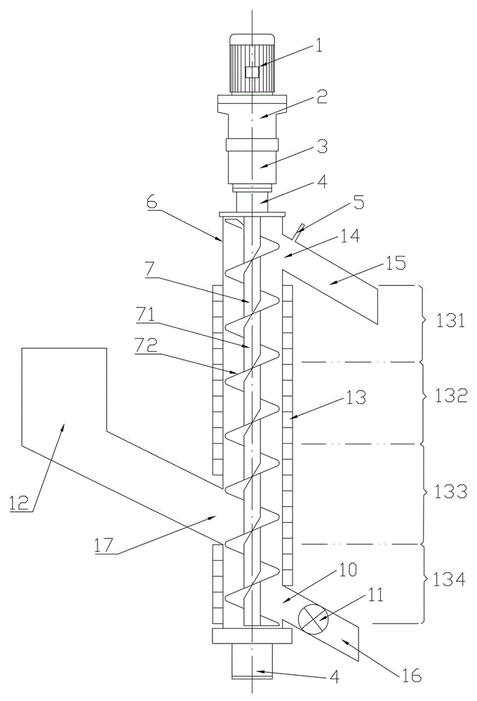
[0024] Such as figure 1 As shown, the magnetic separator of the present invention includes a beneficiation chamber 6 for ore pulp to pass through, a magnetic separation assembly 13 is fixed on the outer wall of the beneficiation chamber 6, and a magnetic separation assembly 13 is fixed on the outer wall of the beneficiation chamber 6. The magnetic material is pushed out of the pushing part 7 of the beneficiation chamber 6 . After the pulp enters the beneficiation chamber 6, the magnetic materials in it are captured by the magnetic force of the magnetic separation assembly 13, forming a material layer with a certain thickness on the inner wall of the beneficiation chamber 6, and pushed out of the beneficiation chamber 6 by the pushing member 7.

[0025] In this embodiment, the pushing member 7 includes a rotating shaft 71 pierced in t...


PUM


Abstract

The invention discloses a magnetic separator. The magnetic separator comprises an ore dressing cavity through which ore pulp passes, wherein a magnetic separating component is fixed at the outer wall of the ore dressing cavity; and a pushing component for pushing a magnetic material absorbed at the inner wall of the ore dressing cavity out of the ore dressing cavity is arranged inside the ore dressing cavity. The magnetic separator has the advantages that the magnetic separator is simple and compact in structure, small in floor area, high in magnetic energy utilization rate, small in physical inclusion of magnetic concentrate, low in magnetic iron loss rate of magnetic tailings, high in ore dressing efficiency and the like.

Description

technical field [0001] The invention mainly relates to the field of mining equipment, in particular to a magnetic separator for magnetite-type iron ore. Background technique [0002] With the rapid development of the iron and steel industry, the demand for iron ore in China has increased dramatically. At present, the iron ore self-sufficiency rate required by my country's iron and steel industry is less than 50%. With the recent rapid development of my country's iron and steel industry, the serious shortage of iron ore resources has become a "bottleneck" restricting the development of my country's iron and steel industry. [0003] China's iron ore resources are abundant but not rich, the reserves rank fourth in the world, and more than 95% are lean ore. Among them, the magnetite type accounts for more than 55%, and the other more than 25% is complex refractory iron oxide ores such as fine-grained hematite and low-grade limonite, siderite, etc., which must be roasted by mag...

Claims


Application Information

Patent Timeline
Patent Type & Authority Patents(China)
IPC IPC(8): B03C1/14
Inventor 彭泽友陈雯
Owner CHANGSHA RES INST OF MINING & METALLURGY
Why Eureka
Try Eureka