
Non-contact electroscope and electroscope method

A non-contact electroscope technology, which is applied in the field of non-contact electroscope and electroscope, can solve the problems that affect the detection accuracy and safety hazards, and achieve the effect of eliminating safety hazards and improving detection accuracy

Inactive Publication Date: 2015-11-18
STATE GRID CORP OF CHINA +3
View PDF6 Cites 0 Cited by
  • Summary
  • Abstract
  • Description
  • Claims
  • Application Information

AI Technical Summary

Problems solved by technology

[0006] In order to solve the problem in the prior art that even when the object to be tested is not charged, the sensor will detect the electric field, thereby affecting the accuracy of the detection and posing potential safety hazards, the embodiment of the present invention provides a non-contact electroscope and electroscope method

Method used


Image

  • Non-contact electroscope and electroscope method
  • Non-contact electroscope and electroscope method
  • Non-contact electroscope and electroscope method

Examples


Embodiment 1

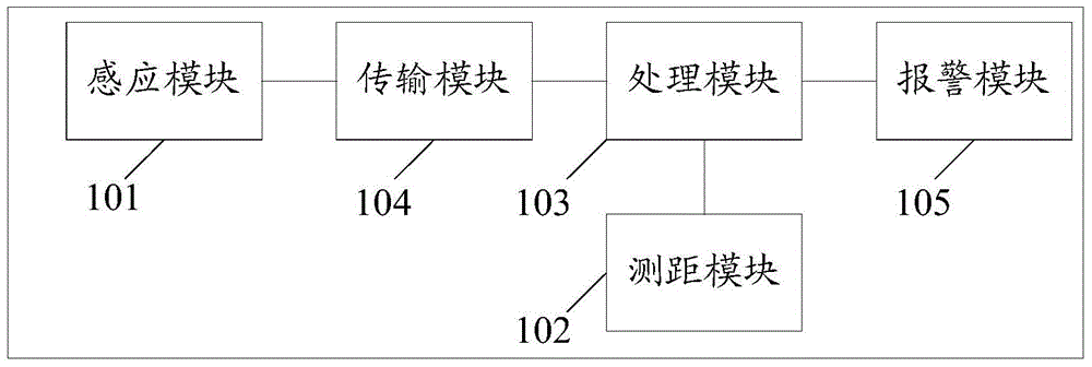
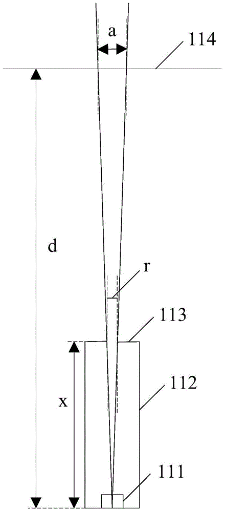
[0034] An embodiment of the present invention provides a non-contact electroscope, which is especially suitable for conducting electroscopes on ultra-high voltage objects to be tested such as high voltage lines, see Figure 1-2 , the electroscope consists of:

[0035] Induction module 101, used to detect the electric field strength of the object to be measured;

[0036] A ranging module 102, configured to detect the distance from the electroscope to the object to be measured;

[0037] The processing module 103 is configured to determine whether the object to be measured is charged according to the measured distance from the electroscope to the object to be measured and the measured electric field strength.

[0038] Specifically, the processing module 103 obtains the preset electric field strength corresponding to the measured distance from the electroscope to the object to be measured according to the corresponding relationship between the distance and the electric field stre...

Embodiment 2

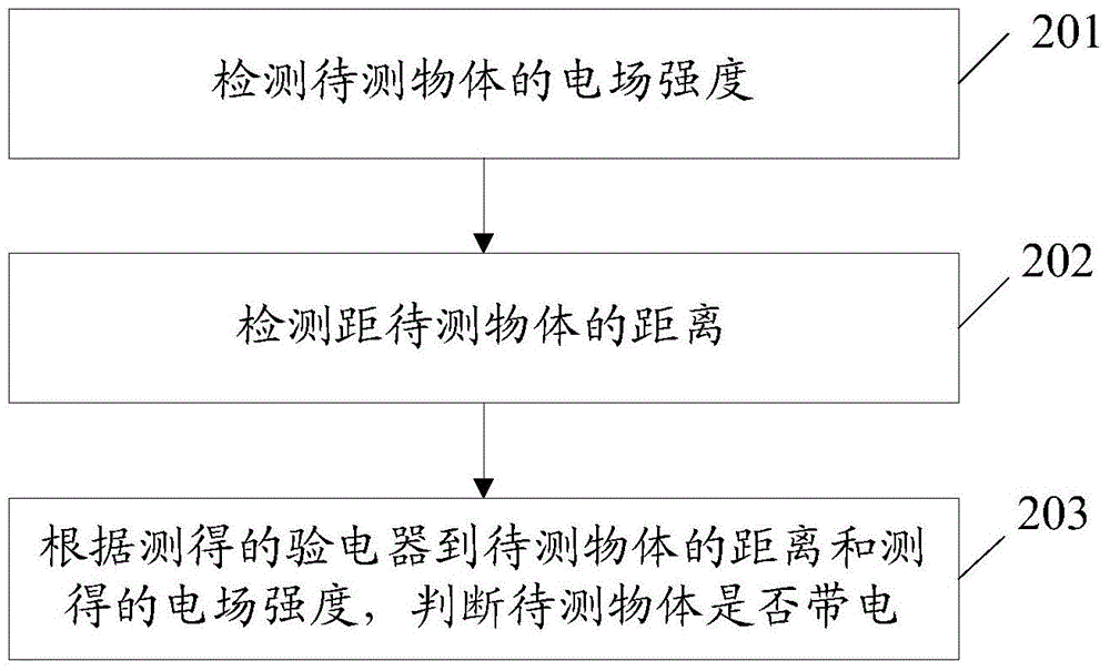
[0056] The embodiment of the present invention provides a non-contact electrical inspection method, which is especially suitable for electrical inspection of UHV objects such as high-voltage lines, see figure 2 , the method includes:

[0057] Step 201: Detect the electric field strength of the object to be measured;

[0058] Step 202: Detect the distance from the electroscope to the object to be measured;

[0059] Step 203: According to the measured distance from the electroscope to the object to be measured and the measured electric field strength, determine whether the object to be measured is charged.

[0060] Specifically, according to the corresponding relationship between the distance and the electric field strength, the preset electric field strength corresponding to the measured distance from the electroscope to the object to be measured is obtained, and the measured electric field strength is compared with the preset electric field strength. When the measured When ...


PUM


Abstract

The invention discloses a non-contact electroscope and an electroscopy and belongs to the field of electrical equipment. The electroscope comprises an inducing module, a distance measurement module and a processing module. The inducing module is used for detecting electric field intensity of an object to be detected. The distance measurement module is used for detecting the distance between the electroscope and the object to be detected. The processing module is used for judging whether the object to be detected is electrified or not according to the detected distance between the electroscope and the object to be detected and the detected electric field intensity. Due to the fact that the non-contact electroscope judges whether the object to be detected is electrified or not according to the electric field intensity of the object to be detected, the distance between the electroscope and the object to be detected and the corresponding relation between the distance and the electric field intensity, the situation that due to influences of the ambient environment, detection accuracy is low is avoided, detection accuracy is improved, and potential safety hazards are eliminated.

Description

technical field [0001] The invention relates to the field of electric equipment, in particular to a non-contact electroscope and an electroscope method. Background technique [0002] An electroscope is an instrument used to test whether an object is charged. According to the electroscope mode, the electroscope can be divided into a contact electroscope and a non-contact electroscope. [0003] Among them, the non-contact electroscope is a new type of electroscope, which is not directly in contact with the object to be measured, and is widely used in the electrometry of dangerous objects such as high-voltage lines. There is a non-contact electroscope, which is composed of an electric field sensor, a processing circuit and a signal indication. power or no power information. [0004] In the process of realizing the present invention, the inventor finds that there are at least the following problems in the prior art: [0005] Since the objects around the object to be measured...

Claims


Application Information

Patent Timeline
Patent Type & Authority Patents(China)
IPC IPC(8): G01R19/145G01R29/12
Inventor 姚军杨德志李守文尚亚东杨云苏军虎王胜利陆军唐凯刘义德李栎杨万义许云卫永鹏
Owner STATE GRID CORP OF CHINA
Learn More