
A substation ultrasonic imaging positioning detection device

A positioning detection device, ultrasonic technology, applied in measurement devices, radio wave measurement systems, positioning and other directions, can solve problems such as failure to reproduce, failure to locate, low accuracy, etc., to facilitate fault diagnosis and early warning analysis, and improve safety. Running, the effect of strong mechanical vibration

Active Publication Date: 2018-11-16
NANYANG POWER SUPPLY COMPANY OF STATE GRID HENAN ELECTRIC POWER
View PDF5 Cites 3 Cited by
  • Summary
  • Abstract
  • Description
  • Claims
  • Application Information

AI Technical Summary

Problems solved by technology

However, the substation is also a place with a relatively special environment. When the substation is in operation, people are not allowed to approach the equipment. It is a dangerous area, and personnel are prohibited from approaching during work. It is very difficult to detect its fault defects
During the regular maintenance period, technicians cannot reproduce the fault phenomenon at high voltage. This problem has not been solved. It can only be inferred manually based on experience and large-scale replacement of equipment. However, for the location of abnormal sounds, especially ultrasonic signals , it is difficult to do it by ear alone
However, for a large amount of signal collection, data processing is cumbersome, and the accuracy rate is relatively low. At the same time, the requirements for the device are high, which is not easy to promote and use.

Method used


Image

  • A substation ultrasonic imaging positioning detection device
  • A substation ultrasonic imaging positioning detection device

Examples


specific Embodiment 1

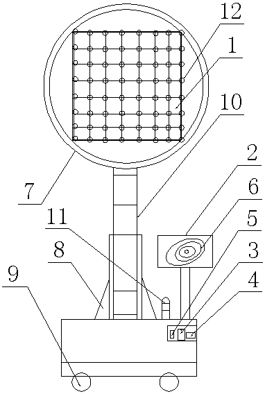
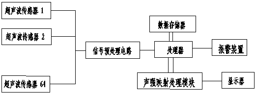
[0030] Such as figure 1 and figure 2 As shown, a substation ultrasonic imaging positioning detection device includes an imaging display mechanism and an ultrasonic detection mechanism connected by a coaxial cable, and the ultrasonic detection mechanism includes ultrasonic sensors 12 arranged in matrix on a quadric surface structure 1 and signal preprocessing circuit.

[0031] The imaging display mechanism includes a display 2, a processor 3 and a data memory 4 connected to the processor 3; the input end of the processor 3 is connected to the output end of the ultrasonic detection mechanism, and the output end of the processor 3 is connected to the Described display 2.

[0032] The processor 3 is provided with a sound intensity mapping processing module 5, and the sound intensity mapping diagram generated by the sound intensity mapping processing module 5 is displayed on the display 2 with pixels of different colors through a threshold circuit, and the same color pixels The c...

specific Embodiment 2

[0039] The only difference from the first embodiment is that the number of ultrasonic sensors 2 on the quadric surface structure 1 is set to 16 or 32.

[0040] In the above-described embodiment, the present invention includes an imaging display mechanism and an ultrasonic detection mechanism connected by a coaxial cable, and the ultrasonic detection mechanism includes an ultrasonic sensor 12 and a signal preprocessing circuit arranged in a matrix on the quadric surface structure 1; the imaging The display mechanism includes a display 2, a processor 3 and a data memory 4 connected to the processor 3; the input of the processor 3 is connected to the output of the ultrasonic detection mechanism, and the output of the processor 3 is connected to the display 2 Gather the spherical wave signal of the vibrating ultrasonic source signal through the ultrasonic sensor 12 on the quadratic surface structure 1, use its three-dimensional structure to locate, combine the signal preprocessing ...


PUM


Abstract

The invention discloses an ultrasonic image positioning detecting device of a transformer substation. The device comprises an image displaying mechanism and an ultrasonic detecting mechanism which are connected through a coaxial cable. The ultrasonic detecting mechanism comprises an ultrasonic sensor and a signal preprocessing circuit which are arranged on a quadric surface structure in a matrix mode. The image displaying mechanism comprises a displayer, a processor and a data memory connected with the processor. The processor is provided with a sound intensity mapping processing module which is used for driving and displaying a sound intensity map to quickly judge an ultrasonic source. According to the position of equipment to be detected in the transformer substation, a cubic data model of a quadric surface is built. A three-dimensional coordination system is built on the basis of the model, and preprocessing and display processing of relative ultrasonic signals are carried out. Ultrasonic imaging is achieved by means of pseudo image information, and fast fault positioning is achieved by means of color ring band analysis. The device effectively improves work efficiency of maintenance of the transformer substation, is simple, convenient and practical, and has good popularization and application value.

Description

technical field [0001] The invention relates to the technical field of ultrasonic positioning equipment, in particular to an ultrasonic imaging positioning detection device for a substation. Background technique [0002] With the refinement of management, humanization of service, and standardization of data in electric power enterprises, the requirements for periodic testing and random testing of the operating status of electrical equipment are getting higher and higher, and the traditional listening and identification has been difficult to solve completely. On-site technical issues; research has found that any electrical equipment in operation, due to the action of alternating current, will produce various sounds and vibrations, including audible noise and ultrasonic waves, which are unique to operating equipment and are A characteristic that indicates the operating state of a device. For example, substations are mostly in an environment with multiple noises, most of which...

Claims


Application Information

Patent Timeline
Patent Type & Authority Patents(China)
IPC IPC(8): G01S5/18
Inventor 张富洲罗道军姚楠李春辉胡志勇张朋飞曹锐
Owner NANYANG POWER SUPPLY COMPANY OF STATE GRID HENAN ELECTRIC POWER
Learn More