Light touch screen and manufacturing method thereof

A manufacturing method and technology of optical touch screen, applied in the direction of instrument, electrical digital data processing, input/output process of data processing, etc. The effect of human-computer interaction

Active Publication Date: 2013-10-09
HEFEI BOE OPTOELECTRONICS TECH +1
View PDF8 Cites 29 Cited by
  • Summary
  • Abstract
  • Description
  • Claims
  • Application Information

AI Technical Summary

Problems solved by technology

But for some large-size screens (for example: 110-inch TV), due to the large display screen, if you use touch to interact, there will b

Method used


Image

  • Light touch screen and manufacturing method thereof
  • Light touch screen and manufacturing method thereof
  • Light touch screen and manufacturing method thereof

Examples


Embodiment 1

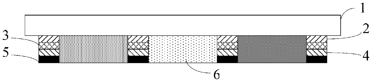
[0039] like figure 1 As shown, the optical touch screen of this embodiment includes: a first electrode layer 2 , a photosensitive material layer 3 and a second electrode layer 4 sequentially formed on a substrate 1 . Since the photosensitive material layer 3 needs to sense the light emitted by the light source, the first electrode layer 2 is a transparent electrode. In order to facilitate the determination of the position illuminated by the light source, the photosensitive material layer 3 is in the shape of a grid, while isolating the first electrode layer 2 and the second electrode layer 4 . Both the first electrode layer 2 and the second electrode layer 4 of the optical touch screen can be plate-shaped transparent electrodes, but the two layers of transparent electrodes reduce the transmittance of the optical touch screen.

[0040] In this embodiment, both the first electrode layer 2 and the second electrode layer 4 are grid-shaped, and the projection of the photosensitive...

Embodiment 2

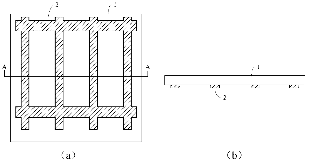
[0065] like Figure 8 As shown, the optical touch screen of this embodiment is basically the same as that of Embodiment 1, except that the transparent first electrode layer 2 is a plate electrode. Compared with Example 1, the transmittance is reduced to a certain extent, but the plate-shaped first electrode layer 2 can play an electrostatic shielding role when no touch occurs, and can prevent external electrical signals from affecting the electrical signals of the display panel. Impact. In terms of the manufacturing method, it is only necessary to make the first transparent electrode layer 2 into a full-surface electrode without etching. The principle of positioning the light emitted by the light source in this embodiment is the same as that in Embodiment 1, and will not be repeated here.

Embodiment 3

[0067] like Figure 9 As shown, the optical touch screen of this embodiment is basically the same as that of Embodiment 1, except that the transparent second electrode layer 4 is a plate electrode. Compared with Example 1, the transmittance is reduced to a certain extent, but the plate-shaped second electrode 4 acts as an electrostatic shield, preventing external electrical signals from affecting the electrical signals of the display substrate. In terms of the manufacturing method, it is only necessary to make the second transparent electrode layer into a plate-shaped electrode layer 4 . The principle of locating the light emitted by the external light source in this embodiment is the same as that in Embodiment 1, and will not be repeated here.

[0068] In the above embodiments, light is emitted by a hand-held light-emitting device, such as a laser pointer. This hand-held lighting device includes:

[0069] The first light emitter and its first control button, the first cont...


PUM


Abstract

The invention relates to the technical field of display, and discloses a light touch screen. The light touch screen comprises a substrate, a first transparent electrode layer, a light-sensitive material layer and a second electrode layer, wherein the first transparent electrode layer, the light-sensitive material and the second electrode layer are formed on the substrate, and the light-sensitive material layer is in a grid shape, insulates the first transparent electrode layer and the second electrode layer, and is used for sensing light illuminated to the light touch screen. The invention further provides a manufacturing method of the light touch screen. According to the light touch screen and the manufacturing method thereof, the position, on the display screen, of the light emitted by a light source can be located by sensing the light emitting by the light source, and therefore human-computer interaction of the light touch screen and a large-screen display device is achieved.

Description

technical field [0001] The invention relates to the field of display technology, in particular to an optical touch screen and a manufacturing method thereof. Background technique [0002] As the latest input and display device, the touch screen is currently the simplest, most convenient and natural way of human-computer interaction, and has been widely used as the display screen of mobile phones, tablets or computers. But for some large-size screens (for example: 110-inch TV), due to the large display screen, if you use touch to interact, there will be places where your fingers cannot or are difficult to touch, such as: the large screen is hung on a high place, It is inconvenient to touch. Contents of the invention [0003] (1) Technical problems to be solved [0004] The technical problem to be solved by the present invention is: how to realize a photosensitive substrate capable of sensing the light emitted by a light source and locating the position of the light on the...

Claims


Application Information

Patent Timeline
IPC IPC(8): G06F3/042
CPCG06F3/042
Inventor 刘荣铖
Owner HEFEI BOE OPTOELECTRONICS TECH
Why Eureka
Try Eureka