
Loudspeaker diaphragm

A loudspeaker and reinforcement technology, applied in the field of electro-acoustics, to prevent shrinkage deformation, reduce distortion, and improve acoustic performance

Active Publication Date: 2013-10-09
GEER INTELLIGENT TECH CO LTD
View PDF6 Cites 5 Cited by
  • Summary
  • Abstract
  • Description
  • Claims
  • Application Information

AI Technical Summary

Problems solved by technology

[0004] In order to solve the above technical problems, the present invention provides a loudspeaker diaphragm, which can make the diaphragm have a higher flatness, reduce the distortion of the product, and improve the acoustic performance of the product

Method used


Image

  • Loudspeaker diaphragm
  • Loudspeaker diaphragm
  • Loudspeaker diaphragm

Examples


Embodiment 1

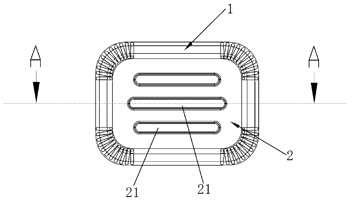
[0029] Such as figure 1 with Figure 4 As shown, the loudspeaker diaphragm includes a diaphragm body part and a rigid composite layer 3 bonded to the center of the diaphragm body part; wherein the diaphragm body part is a single-layer or multi-layer polymer material, which is a relatively flexible structure. It includes a central part 2 at the center and an edge part 3 at the edge. The central part 2 is used to be fixedly combined with the composite layer 3 by means of bonding, etc., and has a planar structure, which is easy to shrink and deform after the main part of the diaphragm is pressed and cooled.

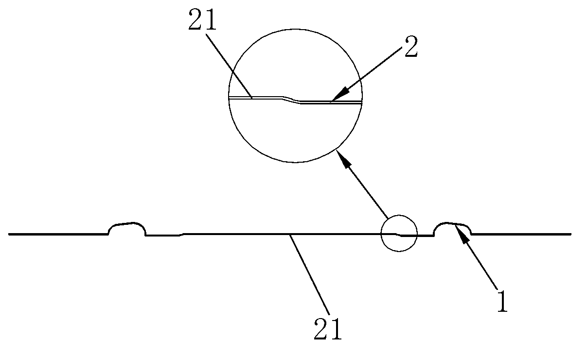
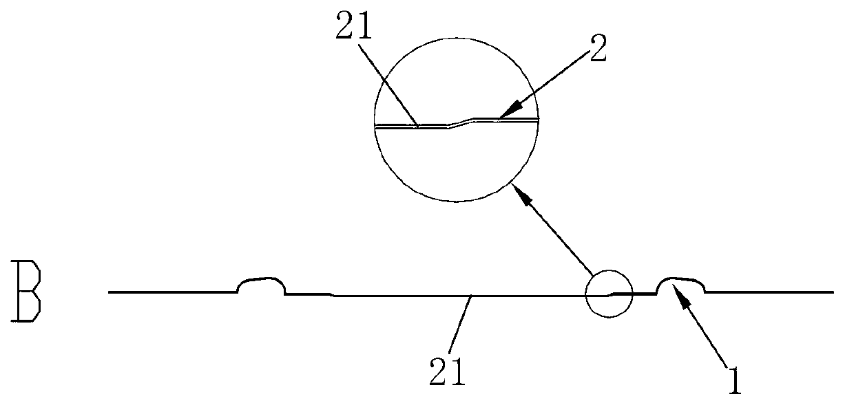
[0030] Such as Figure 1 to Figure 3 As shown, in this embodiment, a convex or concave reinforcing groove 21 with a certain height difference with the central part 2 is provided on the planar central part 2, wherein the thickness of the diaphragm body at the reinforcing groove 21 is the same as the center The thickness of the planar part of part 2 is uniform. After the r...

Embodiment 2

[0036] Such as Figure 10 As shown, the main part of the diaphragm in this embodiment is a hollow ring structure, and the edge is the ring part 1. The inner side of the ring part 1 is provided with a planar central part 2', and the middle part 20' of the central part 2' is a hollow. empty structure. The central part 2' is a ring structure, which is used to fix and combine with the rigid composite layer by means of bonding or the like. The central part 2' of this structure also has defects such as easy deformation after pressing and cooling. Therefore, this embodiment is also provided with a reinforcing groove 21' on this annular central part 2'. The reinforcing groove 21' of this embodiment It is a strip structure arranged along the straight edge of the rectangular vibrating membrane body. Same as the previous embodiment, the reinforcing groove 21' can be a convex or concave structure, the thickness of the diaphragm body at the reinforcing groove 21' is consistent with the t...


PUM


Abstract

The invention discloses a loudspeaker diaphragm. The loudspeaker diaphragm comprises a diaphragm body part and a rigid composite layer at the center position of the diaphragm body part. The diaphragm body part comprises a center part and a bending ring part, wherein the center part is located at the center position and of a plane shape, the bending ring part is located at the border position, and a protrusion or a concave reinforced groove is formed in the position, combined with the composite layer, of center part. The thickness, located at the reinforced groove, of the diaphragm body part is consistent with the thickness of the plane part of the center part. The reinforced groove part and the plane part of the center part are on the same plane after the composite layer and the center part are combined. By the adoption of the structure, the diaphragm can be prevented from shrinking and deforming, flatness of the diaphragm is improved, so that the distorting phenomenon of products is reduced, and acoustic performance of the products is improved.

Description

technical field [0001] The invention relates to the field of electroacoustics, in particular to a loudspeaker diaphragm. Background technique [0002] In the prior art, the loudspeaker diaphragm usually includes a diaphragm body and a rigid composite layer bonded to the center of the diaphragm body. Due to the combination with the composite layer, the existence of the ring part allows the diaphragm to vibrate up and down. At present, the diaphragm body usually adopts a single-layer or multi-layer polymer material structure. The diaphragm body of this polymer material has a certain tension. Since the center part combined with the composite layer is a planar structure, it is manufactured and cooled. The rear center part is easy to shrink and deform, so that the diaphragm is uneven, and the distortion is large during the working process, which affects the product performance. [0003] Therefore, it is necessary to improve the loudspeaker diaphragm of this structure in order t...

Claims


Application Information

Patent Timeline
IPC IPC(8): H04R7/04
Inventor 韩丹杨赟
Owner GEER INTELLIGENT TECH CO LTD
Learn More