
Method for monitoring the use of an electrochemical energy accumulator in a motor vehicle and motor vehicle

A motor vehicle, electrochemical technology, applied in electrochemical generators, vehicle energy storage, current collectors, etc., can solve problems that do not involve the driver

Active Publication Date: 2013-10-09
AUDI AG
View PDF7 Cites 0 Cited by
  • Summary
  • Abstract
  • Description
  • Claims
  • Application Information

AI Technical Summary

Problems solved by technology

[0007] However, the situation where the driver may intentionally cause a deep discharge is not covered here

Method used


Image

  • Method for monitoring the use of an electrochemical energy accumulator in a motor vehicle and motor vehicle

Examples


Embodiment Construction

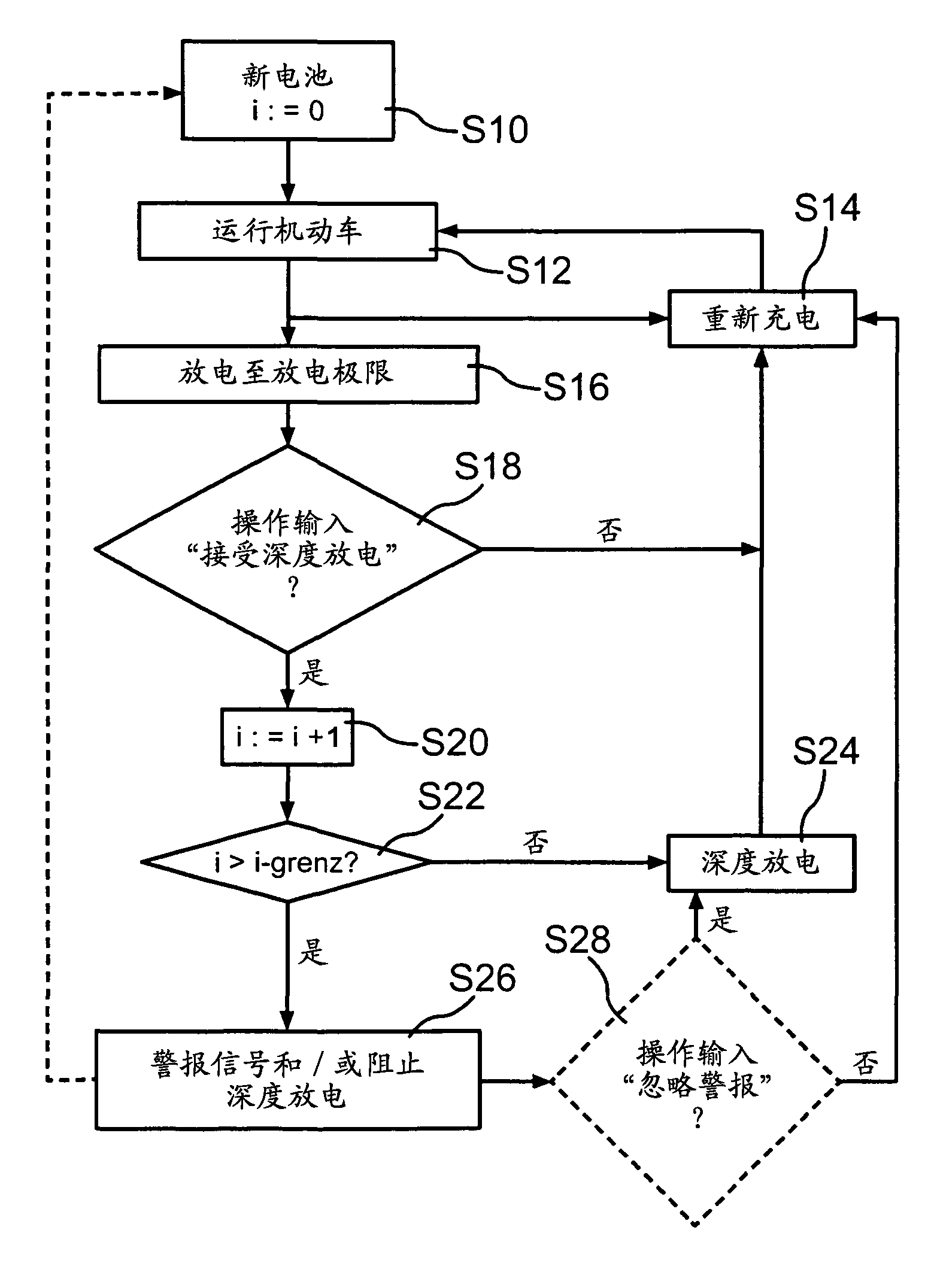
[0025] The method for monitoring the use of a battery in an electric vehicle starts here in step 10 , when the battery is new (for example also because the vehicle itself is new) and the counter i is set to zero.

[0026] The operation of the motor vehicle is then started in step S12. When the motor vehicle is running, the battery is discharged. The battery is either recharged in step S14 before it reaches the discharge limit. It is now of interest what happens when the battery is discharged up to the discharge limit in step S16. The discharge limit is the limit which should not be undershot in normal operation, because otherwise the battery would be damaged if it continues to discharge. However, such a deep discharge should currently be exceptionally permitted by an operator input, for example by the vehicle driver pressing an operator button for this purpose. It is checked in step S18 whether or not such an operation input has occurred. If not, the battery is recharged i...


PUM


Abstract

In a motor vehicle having an electric drive it is to be possible to permit, by means of an operator control input (S18), deep discharge of the electrochemical energy accumulator, which is otherwise forbidden. In the present case, it is counted how often deep discharge has taken place and when a predetermined number of times (i-grenz) is reached, a sequence is preferably triggered, specifically a warning signal is output and / or the subsequent deep discharge is blocked (S26).

Description

technical field [0001] The invention relates to a method for monitoring the use of an electrochemical energy store (battery) in a motor vehicle in which an electric drive is supplied with electricity (current supply). In such motor vehicles, when the electric drive is used, the electrochemical energy store is discharged during operation. The electrochemical energy store can be charged at a charging station to which the vehicle travels. What matters is the state of charge of the electrochemical energy store. The degree to which the accumulator is charged is called the state of charge and is usually expressed as a percentage, where a state of charge of 0% means that the electrochemical accumulator is completely emptied (discharged to the smallest possible degree ), while a state of charge of 100% indicates that the electrochemical energy storage is fully charged. Typically, the percentage is given in proportion to the unit of charge (coulomb). Background technique [0002]...

Claims


Application Information

Patent Timeline
Patent Type & Authority Applications(China)
IPC IPC(8): B60L11/18B60R16/03G01R31/36H01M10/42H02J7/00
CPCH01M2220/20Y02E60/12H02J7/0063H01M10/42H02J7/0029Y02T10/7005B60L11/1861B60L11/1862Y02T10/7011Y02T10/7044H02J2007/004B60L2250/10B60L11/1857H02J2007/0037Y02T10/705B60L11/1859B60L58/16B60L58/14B60L58/13H02J7/00302H02J7/00306B60L58/15Y02T10/70Y02E60/10
Inventor B·里特
Owner AUDI AG
Learn More