Damping arrangement

A damping device and damping technology, applied in the direction of fluid pressure actuators, non-mechanical drive clutches, pipes/pipe joints/pipe fittings, etc., to achieve reliable and fast opening effects

Active Publication Date: 2013-10-09
SCHAEFFLER TECH AG & CO KG
View PDF7 Cites 3 Cited by
  • Summary
  • Abstract
  • Description
  • Claims
  • Application Information

AI Technical Summary

Problems solved by technology

The disadvantage of this construction is that undesir

Method used


Image

  • Damping arrangement
  • Damping arrangement
  • Damping arrangement

Examples


Example Embodiment

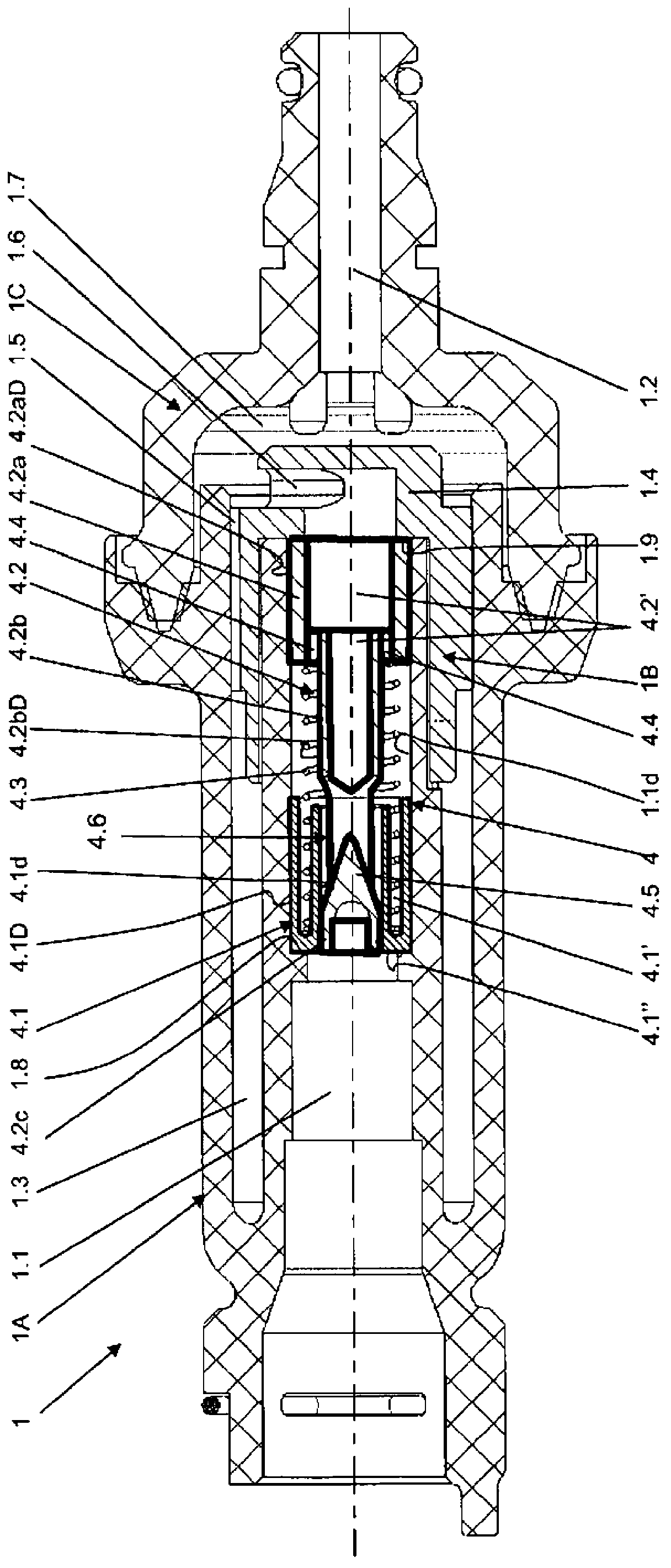
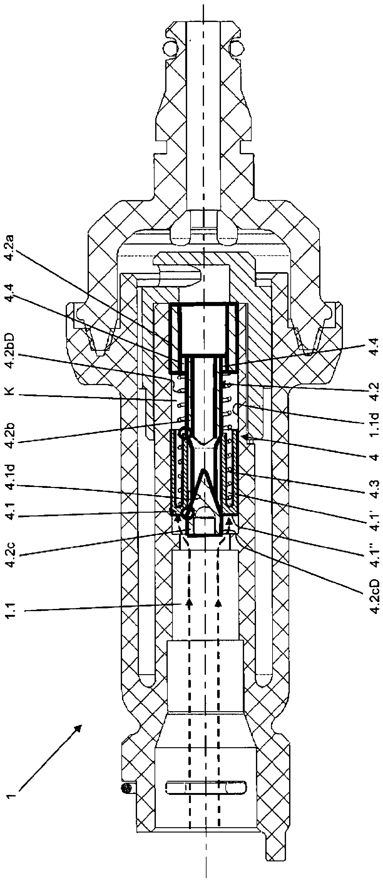
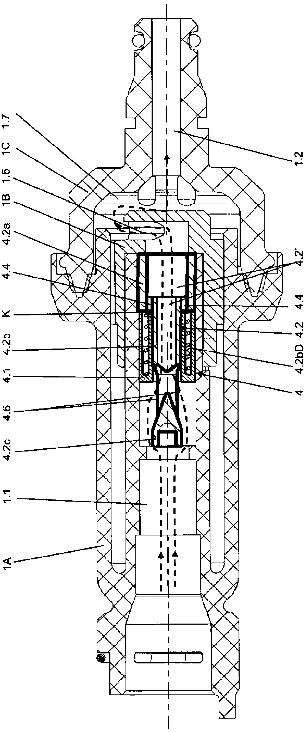
[0025] exist Figures 1 to 3 shows a damping device according to the invention, which consists of a shock absorber 1 for damping vibrations. A shock absorber 1 arranged coaxially to a pressure line (not shown here) is shown in longitudinal section. The shock absorber 1 operating according to the Helmholtz principle consists of three basic components: housing 1A, press-in part 1B and cover 1C. They are arranged concentrically with the through-flow opening 1.1 of the housing 1A or with the through-opening 1.2 of the cover 1C through which fluid can flow. The press-in part 1B is pressed into the annular space 1.3 of the housing 1A and points with its base 1.4 in the direction of the cover 1C. The press-fit part 1B is provided with grooves 1.5 on its outer circumference, which form a supply line to the annular space 1.3. Via a radially outwardly directed opening 1.6 of the press-fit part 1B, there is a connection to a through-opening 1.2 of the cover via a chamber 1.7 of the co...


PUM


Abstract

The invention relates to a damping arrangement for damping/absorbing (figures 1-3) undesired pressure fluctuations in a hydraulic section, in particular for clutch actuation, comprising a master cylinder and a slave cylinder which are hydraulically connected to one another by means of a pressure line through which fluid flows. A damping/absorbing device (1) which is arranged coaxially to the pressure line is used, in which at least one anti-vibration unit (4) combined with a spring is used, and wherein, according to the invention, an additional buffer/damping system is integrated into the anti-vibration unit.

Description

technical field [0001] A damping device for damping / damping undesired pressure oscillations in a hydraulic circuit, in particular for actuating a clutch, comprising a master cylinder and a slave cylinder, which are passed through by a fluid The pressure lines of the pressure lines are hydraulically connected to each other, wherein a damping / vibration damping device arranged coaxially with the pressure lines is used. Background technique [0002] Various vibration damping elements are used in hydraulic systems, in particular in hydraulic sections for actuating clutches in vehicles, to damp undesired pressure oscillations of the hydraulic medium. For this reason, so-called pedal vibration dampers are often used. The pedal vibration damper is a differential pressure valve by means of which low-frequency vibrations can be damped, in particular without additional travel losses, and thus prevent uncomfortable pedal vibrations. [0003] For example, document DE 10106958 A1 disclo...

Claims


Application Information

Patent Timeline
IPC IPC(8): F16D25/08F16D48/02
CPCF15B21/008F16D2048/0215F16D25/088F16D48/02F16D25/08F16D25/12F16L55/041
Inventor P-Y·贝泰勒米L·伊艾兴
Owner SCHAEFFLER TECH AG & CO KG
Why Eureka
Try Eureka