External piezoelectric ceramic variable damping damper

A piezoelectric ceramic and shock absorber technology, applied in shock absorbers, springs/shock absorbers, shock absorbers, etc., can solve the problems of non-controllability of damping values, high prices, changes, etc., to achieve comfort and The effect of taking into account the control, low production and processing costs, and low process complexity

Pending Publication Date: 2019-01-15
清科智能悬架系统(苏州)有限公司
View PDF0 Cites 2 Cited by
  • Summary
  • Abstract
  • Description
  • Claims
  • Application Information

AI Technical Summary

Problems solved by technology

[0003] The second type is a solenoid valve type variable damping shock absorber using an inductance coil. This type of solenoid valve type generally has a large current and a large heat generation, and the existence of the solenoid valve coil inductance limits the electromagnetic valve type variable damping shock absorber. The maximum response speed of the device
However, because the magnetorheological fluid may settle, resulting in uncontrollable changes in the damping value, and even damage to the shock absorber, the industry has been trying to solve such settlement problems; in addition, the nanoparticles in the magnetorheological fluid are harmful to the The production process and production environment have certain requirements. The price of magnetorheological fluid is relatively high at this stage, and high-quality magnetorheological fluid materials are still dependent on imports.

Method used


Image

  • External piezoelectric ceramic variable damping damper
  • External piezoelectric ceramic variable damping damper
  • External piezoelectric ceramic variable damping damper

Examples


Embodiment Construction

[0027] The present invention will be further described below in conjunction with the accompanying drawings. The following examples are only used to illustrate the technical solution of the present invention more clearly, but not to limit the protection scope of the present invention.

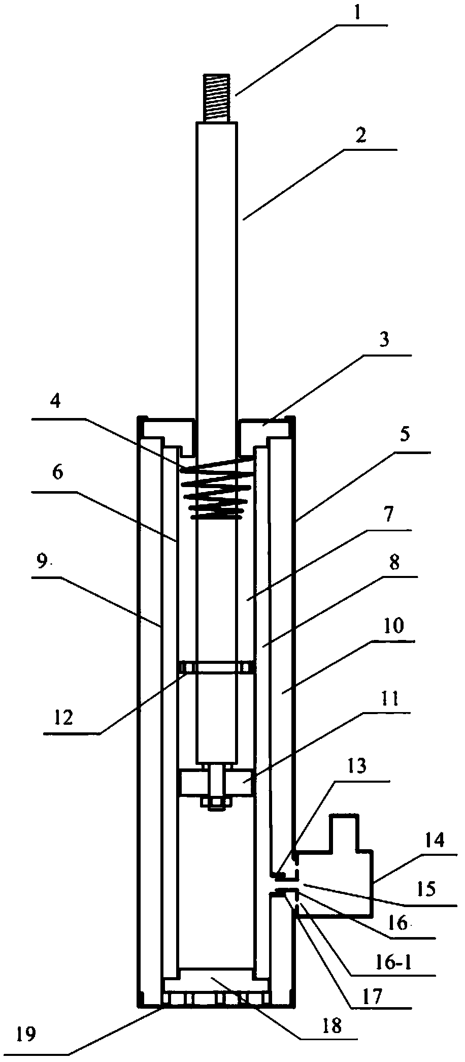
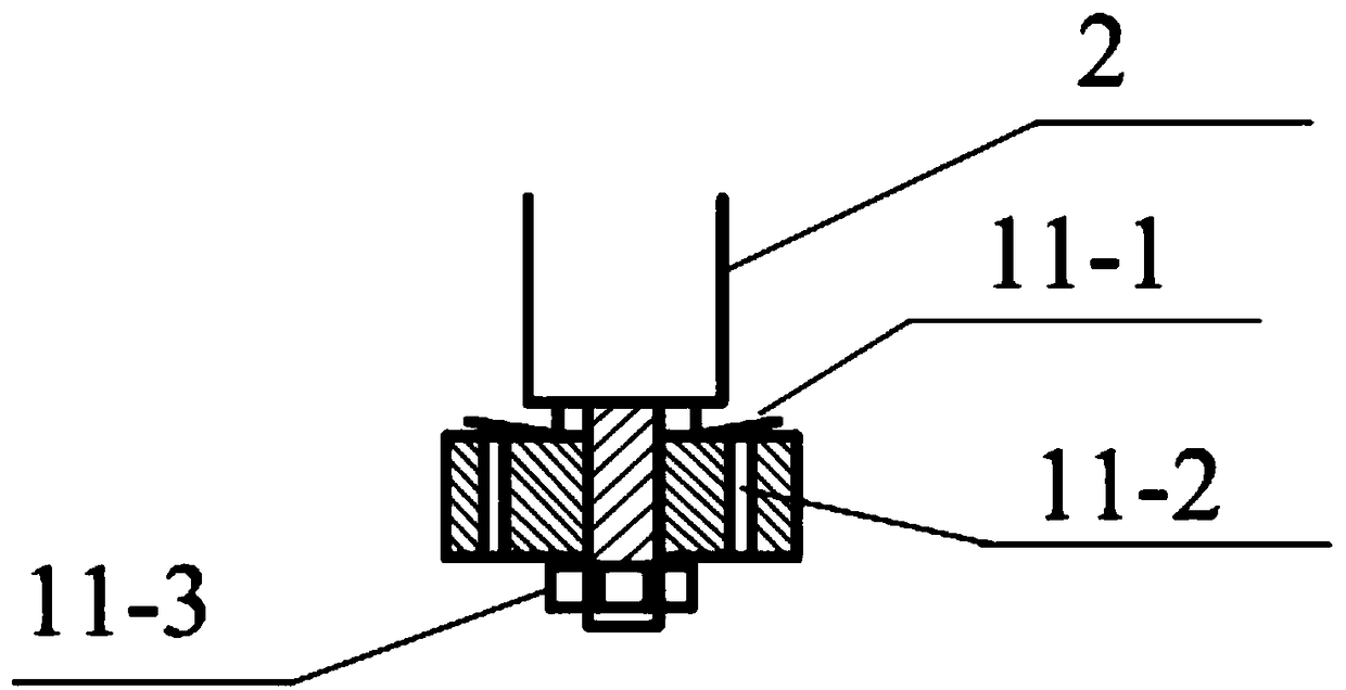
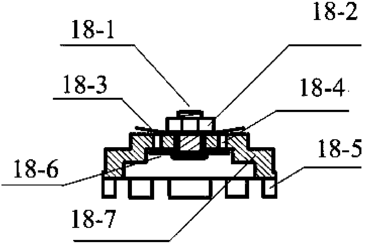
[0028] Such as figure 1 As shown, the external piezoelectric ceramic variable damping shock absorber consists of a threaded fixing part 1, a shock absorber rod 2, a shock absorber sealing cover 3, a limit spring 4, a shock absorber outer cylinder 5, and a shock absorber inner cylinder 6. Shock absorber inner cavity 7, shock absorber middle cavity 8, shock absorber middle barrel 9, shock absorber outer cavity 10, one-way piston valve 11, guide limit card 12, damping valve connecting bridge snap ring 13, Piezoelectric ceramic damping valve 14, liquid flow hole 15, damping valve connecting bridge 16, connecting bridge O-ring 17, one-way bottom valve 18, shock absorber bottom cover 19 are composed. ...


PUM


Abstract

The invention discloses an external piezoelectric ceramic variable damping damper. The damper includes an outer damper cylinder, a middle damper cylinder and an inner damper cylinder, wherein a damperrod penetrates through a damper sealing cover and is then inserted into an inner damper cavity, a one-way piston valve is fixed to a lower end of the damper rod, a guide limit card is arranged on anupper portion of the one-way piston valve on the damper rod, a one-way bottom valve is crimped and sealed with the inner damper cylinder and the middle damper cylinder, a piezoelectric ceramic dampingvalve is disposed outside the outer damper cylinder, a damping valve connecting bridge snap ring is arranged on the middle damper cylinder, the interior of the piezoelectric ceramic damping valve isconnected with the damping valve connecting bridge snap ring through a damping valve connecting bridge, and the damping valve connecting bridge is provided with a connecting bridge overflow hole communicating with an outer damper cavity. Piezoelectric ceramics stacked together are utilized by the piezoelectric ceramic damping valve as an actuator. The damper is advantaged in that the damper is electrically controllable, is with fast response, has the large variable damping ratio and low cost, has high reliability and is not affected by special material processes.

Description

technical field [0001] The invention relates to an external piezoelectric ceramic variable damping shock absorber, which belongs to the field of vehicle variable damping shock absorbers. Background technique [0002] Existing vehicles have the following types of shock absorbers: The first type is the shock absorber with invariable damping, which cannot better balance comfort and handling. A shock absorber with small damping will be more comfortable, but the handling will be worse Worse, the roll angle of the sharp turn is too large, and the pitch angle of the start and stop is also too large, which makes people feel uncomfortable and lacks driving confidence. The shock absorber with large damping has smaller roll and pitch angle, but the comfort is worse and the impact is strong. It can be seen that the variable damping shock absorber that can adjust the damping manually or automatically has become one of the means to solve the comfort and handling. [0003] The second typ...

Claims


Application Information

Patent Timeline
Patent Type & Authority Applications(China)
IPC IPC(8): F16F9/19F16F9/32F16F9/34F16K31/00
CPCF16F9/19F16F9/3207F16F9/3405F16K31/004
Inventor 兰志强
Owner 清科智能悬架系统(苏州)有限公司
Why Eureka
Try Eureka