Centrifugal self-locking damping mechanism and photovoltaic device

A damping mechanism and self-locking technology, applied in photovoltaic modules, photovoltaic power generation, photovoltaic module support structures, etc., can solve problems such as heavy workload, corrosion of damper and damper welds, non-adjustment, etc., to achieve low maintenance costs, Wide range of effects

Pending Publication Date: 2022-02-01
晟维新能源科技发展(天津)有限公司
View PDF0 Cites 0 Cited by
  • Summary
  • Abstract
  • Description
  • Claims
  • Application Information

AI Technical Summary

Problems solved by technology

[0005] a. The service life of the damper is difficult to match the 25-year service life of the tracking bracket, mainly due to the oil leakage of the damper and the corrosion of the weld seam of the damper. It is difficult to achieve 25 years of maintenance-free, and it needs to be replaced after damage, and the later operation and mai

Method used


Image

  • Centrifugal self-locking damping mechanism and photovoltaic device
  • Centrifugal self-locking damping mechanism and photovoltaic device
  • Centrifugal self-locking damping mechanism and photovoltaic device

Examples


Embodiment 1

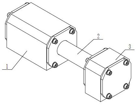
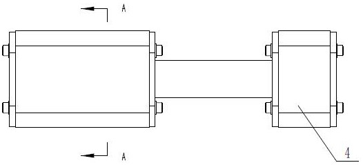
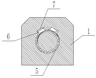
[0024] As shown in the figure, the present invention provides a centrifugal self-locking damping mechanism, including a locking body 1, a cylindrical rotating body 2 and a stabilizing mechanism 3. slot, one end of the rotating body 2 is inserted into the cylindrical slot, and is rotationally connected with the cylindrical slot, and the stabilizing mechanism 3 includes a housing 4 fixed on the frame, the middle part of the housing 4 is provided with a rotating slot, and the rotating body 2 The other end is inserted into the turning groove, and is rotatably connected with the turning groove through the bearing 5. The locking pin part 6 that can slide out to the outside is embedded in the rotating body 2, and at least one set of locking pin parts 6 is provided on the upper part of the cylindrical slot. The matching card slot 7, the front end part of the locking pin part 6 slides out and inserts into the card slot 7 to brake the rotating body 2.

[0025] According to the above-men...

Embodiment 2

[0029] The invention also discloses a centrifugal self-locking photovoltaic device, which includes two sets of centrifugal self-locking damping mechanisms described above. The centrifugal self-locking damping mechanism is fixed on the photovoltaic pile 9 through a horizontal bracket, and also includes a lateral support arm 10, a steel wire rope 11 and a buffer Mechanism 12, the transverse support arm 10 is fixedly connected with the photovoltaic torque tube 8, the two ends of the transverse support arm 10 are rotatably connected with rollers 13, the buffer mechanism 12 is arranged on the horizontal support, the two ends of the steel wire rope 11 are connected with the buffer mechanism 12 and the rotating body 2 connected.

[0030] According to the above embodiment, preferably, the buffer mechanism 12 includes a pull rod 14 and a spring 15, the lower end of the pull rod 14 passes through the horizontal support, and the spring 15 is sleeved on the pull rod 14, the end of the stee...


PUM


Abstract

The invention provides a centrifugal self-locking damping mechanism and a photovoltaic device, and relates to the photovoltaic field. The centrifugal self-locking damping mechanism comprises a locking body and a cylindrical rotating body, the middle part of the locking body is provided with a cylindrical slot matched with the rotating body, one end of the rotating body is inserted into the cylindrical slot and is rotatably connected with the cylindrical slot, a lock pin part capable of sliding out outwards is embedded in the rotating body, at least one group of clamping grooves matched with the lock pin part are formed in the upper part of the cylindrical slot, the front end part of the lock pin part slides out and is inserted into the clamping grooves to brake the rotating body, and when sudden change external acting force is applied to the photovoltaic panel, the photovoltaic panel pulls the rotating body to rotate through the steel wire rope, the lock pin part embedded in the rotating body slides outwards under the action of centrifugal force until the front end part of the lock pin part slides out and is inserted into the clamping groove, and then the rotating body is braked, so the damping effect is achieved, the application range is wide, and the follow-up maintenance cost is low.

Description

technical field [0001] The invention relates to the photovoltaic field, in particular to a centrifugal self-locking damping mechanism and a photovoltaic device. Background technique [0002] Photovoltaic power generation is a technology that directly converts light energy into electrical energy by using the photovoltaic effect of the semiconductor interface. Photovoltaic tracking brackets are an important component of photovoltaic power generation. At present, on a global scale, photovoltaic tracking brackets are used in Gobi, Deserts, tidal flats, grasslands, wastelands and other wild environments away from urban crowds. The climate and environment of the site where it is located is often complex and changeable, and sudden extreme weather may also occur in individual areas, such as strong winds, heavy snow, floods, earthquakes, etc. [0003] In order to ensure a 25-year service life of the photovoltaic tracking bracket in a complex and changeable field environment, the sta...

Claims


Application Information

Patent Timeline
IPC IPC(8): F24S30/425H02S20/32
CPCF24S30/425H02S20/32F24S2030/19Y02E10/47Y02E10/50
Inventor 王伟董旭高鹏
Owner 晟维新能源科技发展(天津)有限公司
Why Eureka
Try Eureka