Pipe bursting shutoff valve

A shut-off valve and pipe burst technology, which is applied in the field of shut-off valves, can solve the problems of difficulty in realizing the adjustment of the control flow size and the like, and achieve the effect of reliable structure.

Active Publication Date: 2013-10-16
CHINA THREE GORGES CORPORATION
7 Cites 6 Cited by

AI-Extracted Technical Summary

Problems solved by technology

The disadvantages are: 1. Because the weight relies on gravity to function, the valve must be arranged horizon...

Abstract

A pipe bursting shutoff valve comprises a valve body which is arranged on a pipe body and communicated with the inner portion of the pipe body. The pipe bursting shutoff valve further comprises a control cavity, a valve shaft, a first elastic component, a diaphragm piston and a valve disc, the first elastic component, the diaphragm piston and the valve disc are arranged on the valve shaft in sequence, the control cavity is connected with the valve body, the valve shaft penetrates through the control cavity to enter the valve body, the diaphragm piston is arranged inside the control cavity, the control cavity is in rigid connection with the diaphragm piston, the control cavity is divided into an independent upper chamber and an independent lower chamber, the valve disc is arranged inside the valve body, the lower chamber is communicated with the pipe body through a lower chamber through pipe, the first elastic component can drive the valve shaft to move along the central line of the valve shaft after being stressed and deformed, and the movement of the valve shaft can enable the diaphragm piston to be deformed in the control cavity to change the size of the upper chamber and the size of the lower chamber, and meanwhile can drive the valve disc to move in the valve body and the pipe body. The pipe bursting shutoff valve has the advantages of being capable of adapting to the normal change of pressure in a pipeline and being mounted by adopting any angle.

Application Domain

Technology Topic

PistonPipe bursting +2

Image

  • Pipe bursting shutoff valve
  • Pipe bursting shutoff valve
  • Pipe bursting shutoff valve

Examples

  • Experimental program(1)

Example Embodiment

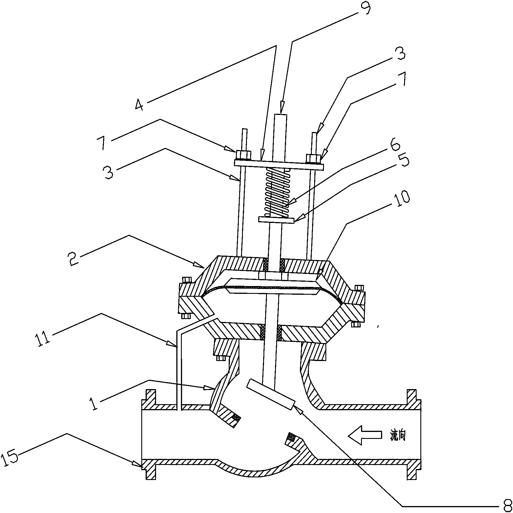
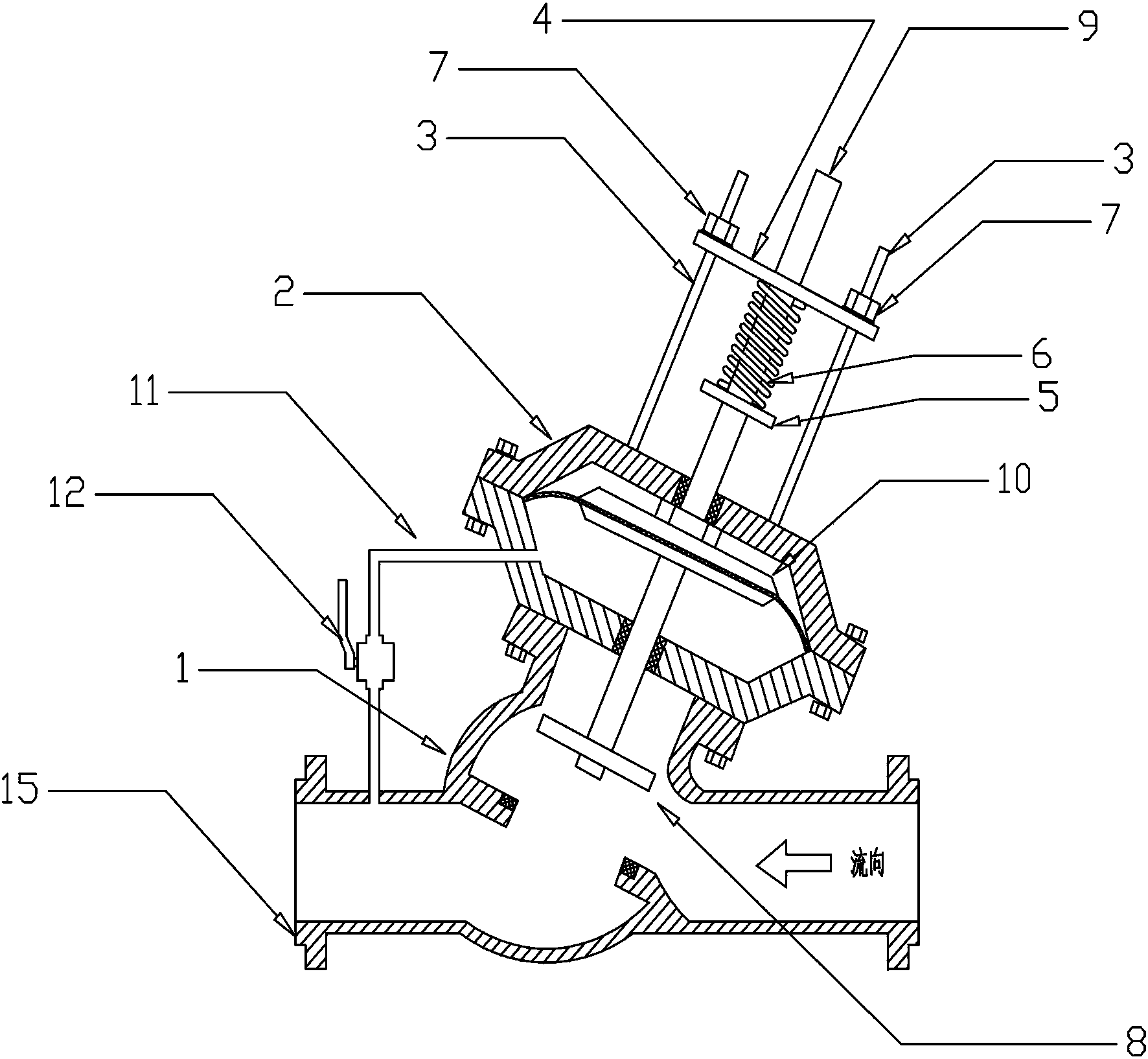
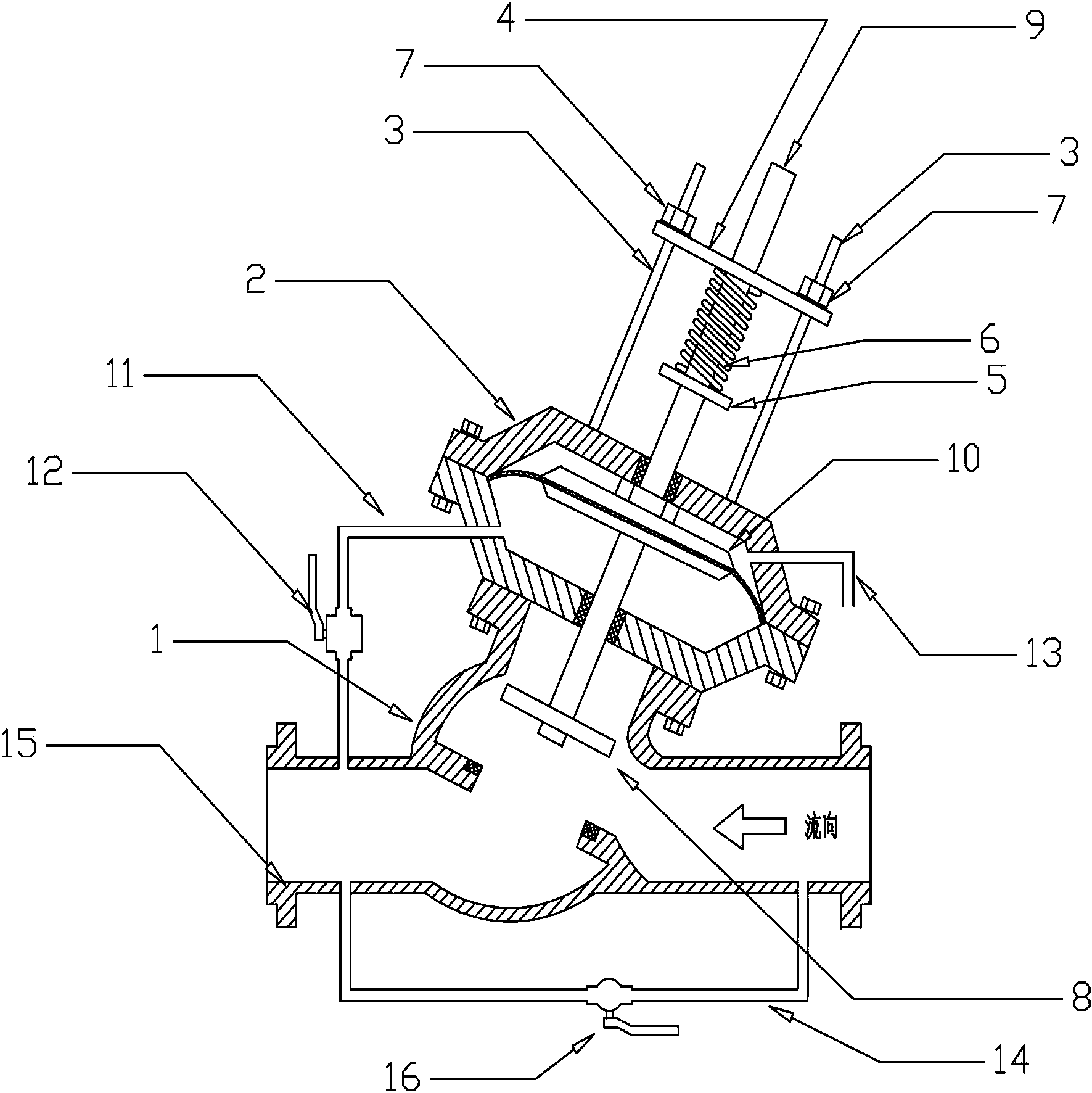
[0021] Such as figure 1 In, a blast pipe shutoff valve includes a valve body 1 arranged on a pipe body 15 to communicate with the inside of the pipe body 15. The blast pipe shutoff valve further includes a control chamber 2, a valve shaft 9, and the valve shaft 9 in turn. The first elastic component on the upper part, the diaphragm piston 10, the valve disc 8, the control chamber 2 is connected with the valve body 1, the valve shaft 9 passes through the control chamber 2 and enters the valve body 1, and the diaphragm piston 10 is provided with In the control chamber 2, the control chamber 2 is rigidly connected with the diaphragm piston 10, and the chamber system 2 is divided into an independent upper chamber and a lower chamber. The valve disc 8 is arranged in the valve body 1, and the lower chamber communicates with the lower chamber. The tube 11 communicates with the tube body 1. The first elastic component includes a spring 6, a screw rod 3, a pressure plate 4, a baffle 5, a spring 6, and an adjusting nut 7. The spring 6 is sleeved on the valve shaft 9 and the baffle 5 is installed On the valve shaft 9, the pressure plate 4 is fixed outside the control chamber 2 by the screw rod 3 and the adjusting nut 7. One end of the valve shaft 9 passes through the pressure plate 4, the spring 6 is arranged between the pressure plate 4 and the baffle 5, and the spring 6 is stressed After deformation, the valve shaft 9 can be driven to move along its centerline; the pipe body 15 is provided with a seat, and the valve disc 8 is placed on the seat to cut off the flow of liquid in the pipe body 15; the centerline of the pipe body 15 and the centerline of the valve body 1 The included angle is 89 degrees; the movement of the valve shaft 9 can deform the diaphragm piston 10 in the control chamber 2 to change the size of the upper chamber and the lower chamber, and at the same time drive the valve disc 8 to move inside the valve body 1 and the tube body 15.
[0022] Such as figure 2 In, a blast pipe shutoff valve includes a valve body 1 arranged on a pipe body 15 to communicate with the inside of the pipe body 15. The blast pipe shutoff valve further includes a control chamber 2, a valve shaft 9, and the valve shaft 9 in turn. The first elastic component on the upper part, the diaphragm piston 10, the valve disc 8, the control chamber 2 is connected with the valve body 1, the valve shaft 9 passes through the control chamber 2 and enters the valve body 1, and the diaphragm piston 10 is provided with In the control chamber 2, the control chamber 2 is rigidly connected with the diaphragm piston 10, and the chamber system 2 is divided into an independent upper chamber and a lower chamber. The valve disc 8 is arranged in the valve body 1, and the lower chamber communicates with the lower chamber. The tube 11 is in communication with the tube body 1, the lower cavity through tube 11 is provided with a throttle valve 12, the first elastic component includes a spring 6, a screw rod 3, a pressure plate 4, a baffle 5, a spring 6, an adjusting nut 7, and the spring 6 is sleeved on the valve shaft 9, the baffle 5 is installed on the valve shaft 9, the pressure plate 4 is fixed outside the control chamber 2 by the screw rod 3 and the adjusting nut 7, the valve shaft 9 passes through the pressure plate 4, and the spring 6 is set on the pressure plate Between 4 and baffle 5, the spring 6 can drive the valve shaft 9 to move along its centerline after being deformed by the force; the pipe body 15 is provided with a seat, and the valve disc 8 can be placed on the seat to cut off the flow of liquid in the pipe body 15 ; The angle between the centerline of the tube body 15 and the centerline of the valve body 1 is 45 degrees; the movement of the valve shaft 9 can deform the diaphragm piston 10 in the control chamber 2 to change the size of the upper chamber and the lower chamber, and drive the valve disc at the same time 8 moves inside the valve body 1 and the pipe body 15.
[0023] Such as image 3 As shown, a blasting pipe shut-off valve includes a valve body 1 arranged on a pipe body 15 and communicating with the inside of the pipe body 15. The blasting pipe shut-off valve further includes a control chamber 2, a valve shaft 9, a flat pressure pipe 14, and a valve body 1 arranged in sequence. On the valve shaft 9, the first elastic component, the diaphragm piston 10, the valve disc 8, and the flat pressure tube 14 are connected to the tube body 15 at one end, and upstream of the connection between the valve body 1 and the tube body 15, and the other end to the tube body 15 The connection point is downstream of the connection between the valve body 1 and the pipe body 15, and a valve 16 is provided on the flat pressure pipe 14; the control chamber 2 is connected with the valve body 1, and the valve shaft 9 enters through the control chamber 2 In the valve body 1, the diaphragm piston 10 is arranged in the control chamber 2. The control chamber 2 and the diaphragm piston 10 are rigidly connected, and the cavity system 2 is divided into an independent upper chamber and a lower chamber. The valve disc 8 is arranged in the valve In the body 1, the lower chamber communicates with the tube body 1 through the lower chamber through tube 11, and the lower chamber through tube 11 is provided with a throttle valve 12. The first elastic component includes a spring 6, a screw rod 3, a pressure plate 4, and a baffle 5. , Spring 6, adjusting nut 7, the spring 6 is sleeved on the valve shaft 9, the baffle 5 is installed on the valve shaft 9, the pressure plate 4 is fixed outside the control chamber 2 through the screw rod 3 and the adjusting nut 7, the valve shaft 9 One end passes through the pressure plate 4, and the spring 6 is arranged between the pressure plate 4 and the baffle 5. The spring 6 can drive the valve shaft 9 to move along its centerline after being deformed by the force; the pipe body 15 is provided with a seat and the valve disc 8 is placed The pedestal can cut off the flow of liquid in the tube body 15; the angle between the center line of the tube body 15 and the center line of the valve body 1 is 45 degrees; the movement of the valve shaft 9 can make the diaphragm piston 10 deform in the control chamber 2 and change the upper chamber With the size of the lower chamber, it can drive the valve disc 8 to move inside the valve body 1 and the tube body 15 at the same time.
[0024] Working principle: The pre-tightening force of the spring 6 can be adjusted by adjusting the nut 7 to adjust the pressure setting value of the pipe body 1 when the burst pipe shutoff valve is closed.
[0025] In order to achieve the above working principle, the relationship between the parameters is:
[0026] During normal operation: P2·A>K1+f
[0027] When the valve is closed: P1·A
[0028] Among them: the preload of spring 6 when the blast pipe shutoff valve is fully opened——K1, the preload of spring 6 when the blast pipe shutoff valve is fully closed——K2, the effective cross-sectional area of ​​the diaphragm piston 10——A, the blast pipe shuts off When the valve starts to close, the pressure of the pipe body is 15—P1, the pressure of the pipe when the burst shutoff valve starts to open—P2, and the friction of the shaft seal—f.
[0029] Therefore, in a steady state, the pipeline pressure interval when the valve is closed is (0, P1), and the pipeline pressure interval when the valve is opened is (P2, ∞), that is, the valve closes when the pipeline pressure is less than P1, and opens when it is greater than P2.
[0030] When the pipeline is normally supplied with water or other liquids, the pressure of the pipe body 15 before and after the valve body 1 and the pressure of the lower chamber of the control chamber 2 are equal, and the axial force generated by the diaphragm piston is greater than the sum of the preload force of the spring 6 and the friction force of the shaft seal. The valve disc 8 is in the valve body 1, and the pipe body 15 is in a fully open state;
[0031] When the pipe burst occurs, the pressure of the front and back of the pipe burst shutoff valve and the lower chamber of the control chamber 2 drops sharply. When the preload force of the spring 6 is greater than the sum of the axial force of the diaphragm piston 19 and the friction force of the shaft seal, the valve disc 8 and the valve stem 9 Start moving down. In the process of closing, due to the combined force of the fluid impact on the valve disc 8 and the pressure of the spring 6, the valve disc 8 continues to move until it is fully closed.
[0032] When the pipe burst accident is handled, open valve 15 and fill the pipe behind valve body 1 with water through the flat pressure pipe 14. When the pipe pressure gradually recovers behind valve body 1, the pressure in the lower chamber of control chamber 2 increases, pushing diaphragm piston 10 , The valve shaft 9 and the valve disc 8 move upwards until they are fully opened. Finally, the valve 15 is closed and the pipe body 15 returns to its normal working state.
[0033] By adjusting the throttle valve 12, the flow rate of the upper chamber connecting pipe 13 can be controlled to reduce the inlet and outlet flow of the lower chamber of the control chamber 2, thereby reducing the closing speed of the valve disc 8 and delaying time (for example, to prevent misoperation) And reduce the impact of water hammer.
[0034] The structure in this example is only an illustration and explanation of the claims, so as to facilitate the public's reading and understanding, and should not be regarded as a limitation to the claims. The protection scope of the present invention should be subject to the scope of the claims and the legal equivalents. .

PUM

no PUM

Description & Claims & Application Information

We can also present the details of the Description, Claims and Application information to help users get a comprehensive understanding of the technical details of the patent, such as background art, summary of invention, brief description of drawings, description of embodiments, and other original content. On the other hand, users can also determine the specific scope of protection of the technology through the list of claims; as well as understand the changes in the life cycle of the technology with the presentation of the patent timeline. Login to view more.

Similar technology patents

Suction base for intelligent nursing toilet bowl

ActiveCN104382519AReliable structureAutomatically adjusts for comfortBathroom accessoriesTraffic volumeSpray nozzle
Owner:CRRC SHANDONG CO LTD

Classification and recommendation of technical efficacy words

Why Eureka
Try Eureka