Adaptive chip breaker for heavy turning

A self-adaptive, chip breaker technology, applied in the parts of boring machine/drilling machine, metal processing equipment, drilling/drilling equipment, etc., can solve the problem of easy generation of C-shaped chips and σ-shaped chips, long indexable tool cycle , the problem of high research and development costs, to achieve the effect of improving production efficiency, reducing production costs, and strong versatility

Inactive Publication Date: 2013-10-23
HARBIN UNIV OF SCI & TECH
View PDF5 Cites 1 Cited by
  • Summary
  • Abstract
  • Description
  • Claims
  • Application Information

AI Technical Summary

Problems solved by technology

[0006] The purpose of the present invention is to provide an adaptive chip breaker for heavy-duty turning to solve the problem of easy generation of C-shaped chips and σ-shaped chips in the process of heavy-duty cutting using the prior art and the long cycle time and research and development costs of developing indexable tools with chip breakers. High and narrow use range

Method used


Image

  • Adaptive chip breaker for heavy turning
  • Adaptive chip breaker for heavy turning
  • Adaptive chip breaker for heavy turning

Examples


specific Embodiment approach 1

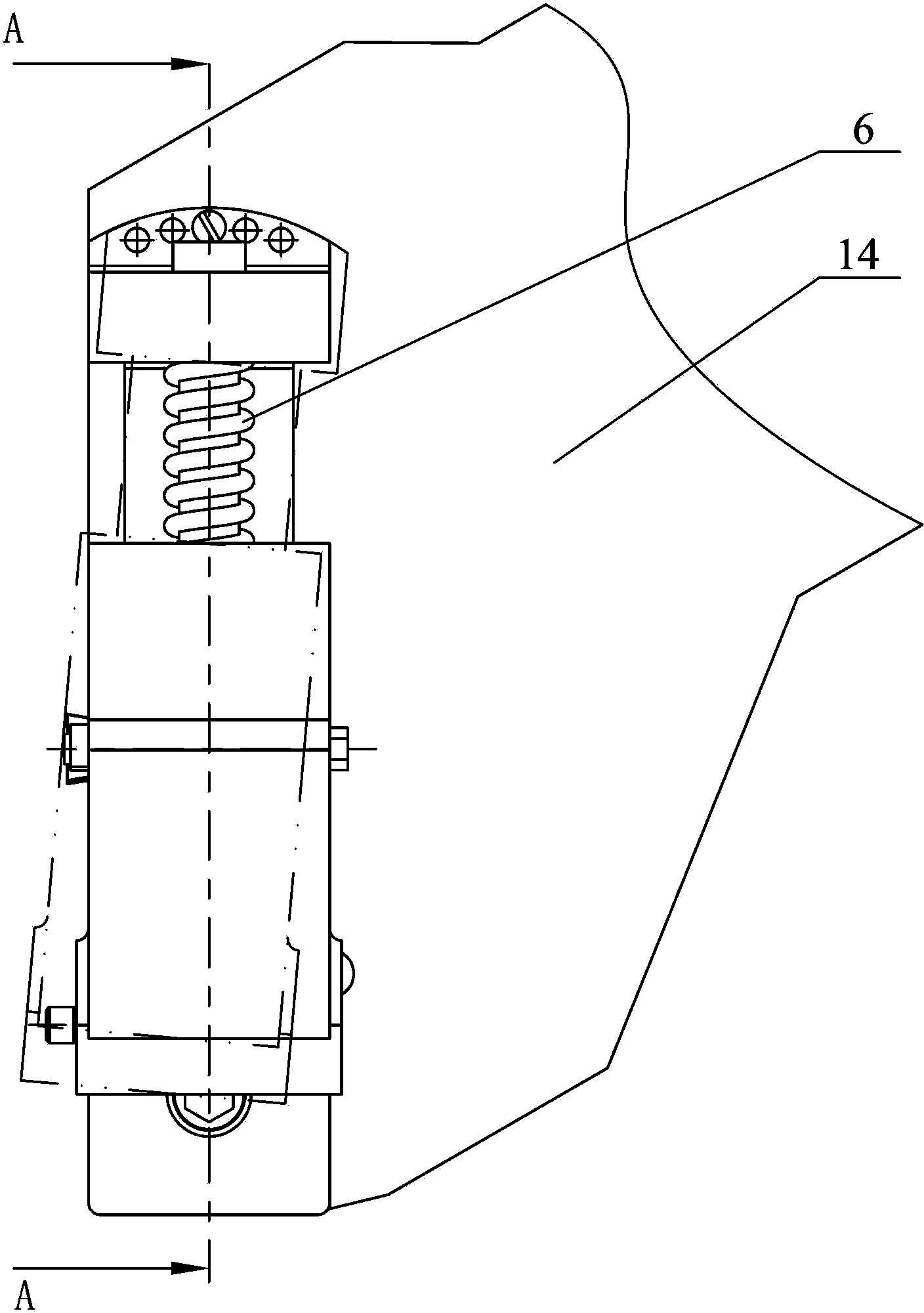
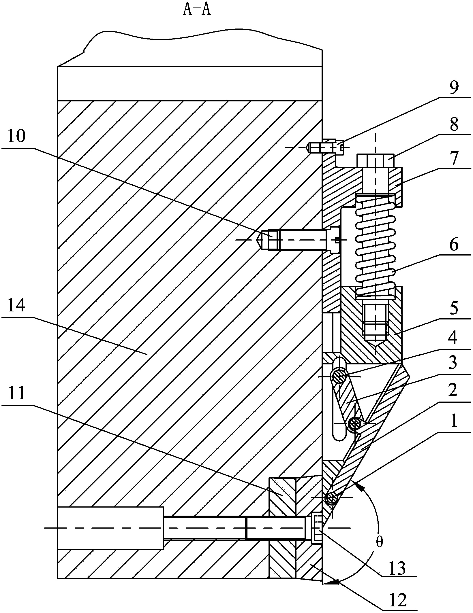
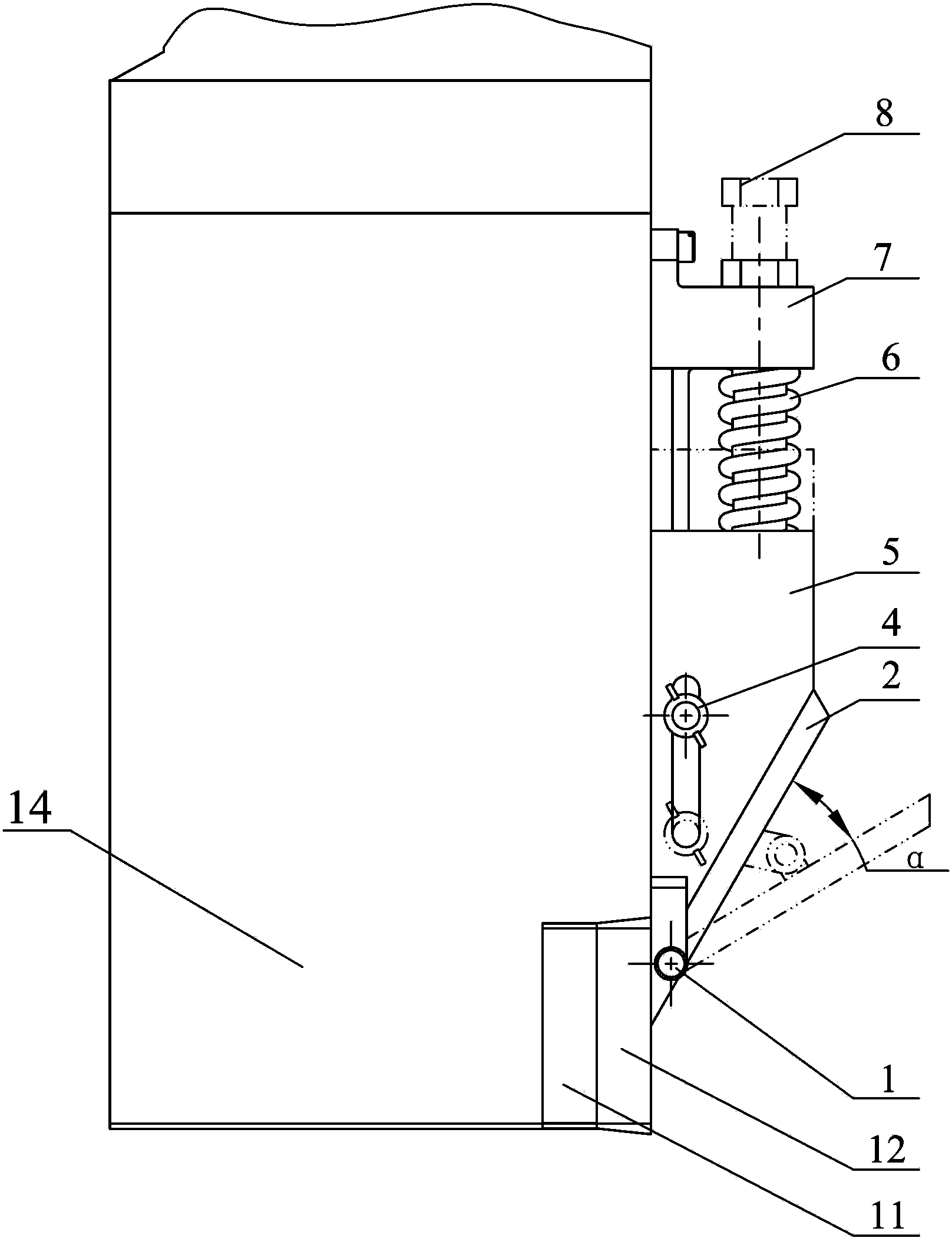
[0012] Specific implementation mode one: as Figure 1-Figure 11 As shown, the heavy-duty turning adaptive chip breaker of this embodiment is characterized in that it includes a stopper positioning bolt 1, a stopper 2, a push rod 3, a sliding limit bolt 4, a slider 5, a compression spring 6, a base 7. Damping adjustment bolt 8, angle limit bolt 9, center rotation bolt 10, gasket 11, blade 12, blade fastening bolt 13;

[0013] The base 7 includes a horizontal plate 7-1 and an upright plate 7-2, the rear end of the upright plate 7-2 is affixed to the front surface of the horizontal plate 7-1, the horizontal plate 7-1 is arranged on the front surface of the turning bar 14, and the horizontal The plate 7-1 is positioned at the upper end to be provided with a plurality of angle adjustment holes 7-3, and the central connection line of the plurality of angle adjustment holes 7-3 is an arc line protruding to the upper end of the base 7, and the front surface of the turning tool bar 14 ...

specific Embodiment approach 2

[0014] Specific implementation mode two: combination figure 2 and image 3 Note that the adjustment range of the angle between the edge of the front end surface of the slider 5 and the main cutting edge of the blade 12 in this embodiment is ±20°. That is, the angle range between the limit position of the slider 5 turning left and the limit position turning right is ±20°. Therefore, the present invention can effectively adapt to the cutting conditions of the left and right forms in the actual production and processing process. The undisclosed technical features in this embodiment are the same as those in the first embodiment.

specific Embodiment approach 3

[0015] Specific implementation mode three: combination Figure 2 to Figure 5 And to illustrate, the lower end of the slider 5 in this embodiment is provided with a chute opening backward, and the chute of the slider 5 is slidably connected to the horizontal plate 7-1 of the base 7 . The undisclosed technical features in this embodiment are the same as those in the first or second specific embodiment.


PUM


Abstract

The invention discloses an adaptive chip breaker for heavy turning, belongs to the technical field of turning tools, and solves the problems of high possibility of generating C-shaped chips and sigma-shaped chips in a heavy turning process and long development cycle, high research and development expense and narrow application range of an indexable cutting tool of a chip breaking groove in the prior art. An angle adjusting hole of a horizontal plate is in threaded connection with a second threaded hole of a turning tool rod through an angle limiting bolt; the horizontal plate is in threaded connection with the turning tool rod through a central rotary bolt; a sliding block is glidingly arranged on the horizontal plate; a damping adjusting bolt penetrates through a vertical plate to be in threaded connection with the sliding block; a compression spring is arranged on the damping adjusting bolt in a sleeving manner; a baffle block is connected with the sliding block through a baffle block positioning bolt; the baffle block can rotate around the baffle block positioning bolt; one end of a push rod is glidingly connected with the sliding block; the other end of the push rod is hinged to the side surface of the baffle block; a gasket, a blade and the turning tool rod are fixedly connected through blade fastening bolts. The adaptive chip breaker is used for turning a workpiece.

Description

technical field [0001] The invention belongs to the technical field of turning processing tools, in particular to an adaptive chip breaker for heavy turning. Background technique [0002] The cutting depth and feed rate of heavy-duty cutting are very large, and the removal of rough material is as high as 50% or more, which is a typical irreversible process with high material removal rate. During processing, metal materials are accompanied by plastic deformation and fracture caused by large strain and high temperature, often forming C-shaped chips and σ-shaped chips. A large amount of debris brings great inconvenience to the cleaning work, increases the auxiliary production time, and seriously restricts the improvement of production efficiency, which has become an important issue in heavy-duty cutting. Chip control in heavy-duty cutting is to obtain a stable and continuous cutting process to protect the machined surface, enhance production safety and facilitate chip cleaning...

Claims


Application Information

Patent Timeline
Patent Type & Authority Applications(China)
IPC IPC(8): B23B47/34B23B47/00
Inventor 刘献礼岳彩旭严复钢程耀楠胡强孙守慧刘利
Owner HARBIN UNIV OF SCI & TECH
Why Eureka
Try Eureka