
Pneumatic tire

A technology for pneumatic tires and treads, applied in tire parts, wheels, tire treads/tread patterns, etc., can solve the problems of poor ground contact, partial wear, insufficient edge effect, etc., to improve edge effect, improve The effect of braking performance

Active Publication Date: 2013-10-23
TOYO TIRE & RUBBER CO LTD
View PDF3 Cites 2 Cited by
  • Summary
  • Abstract
  • Description
  • Claims
  • Application Information

AI Technical Summary

Problems solved by technology

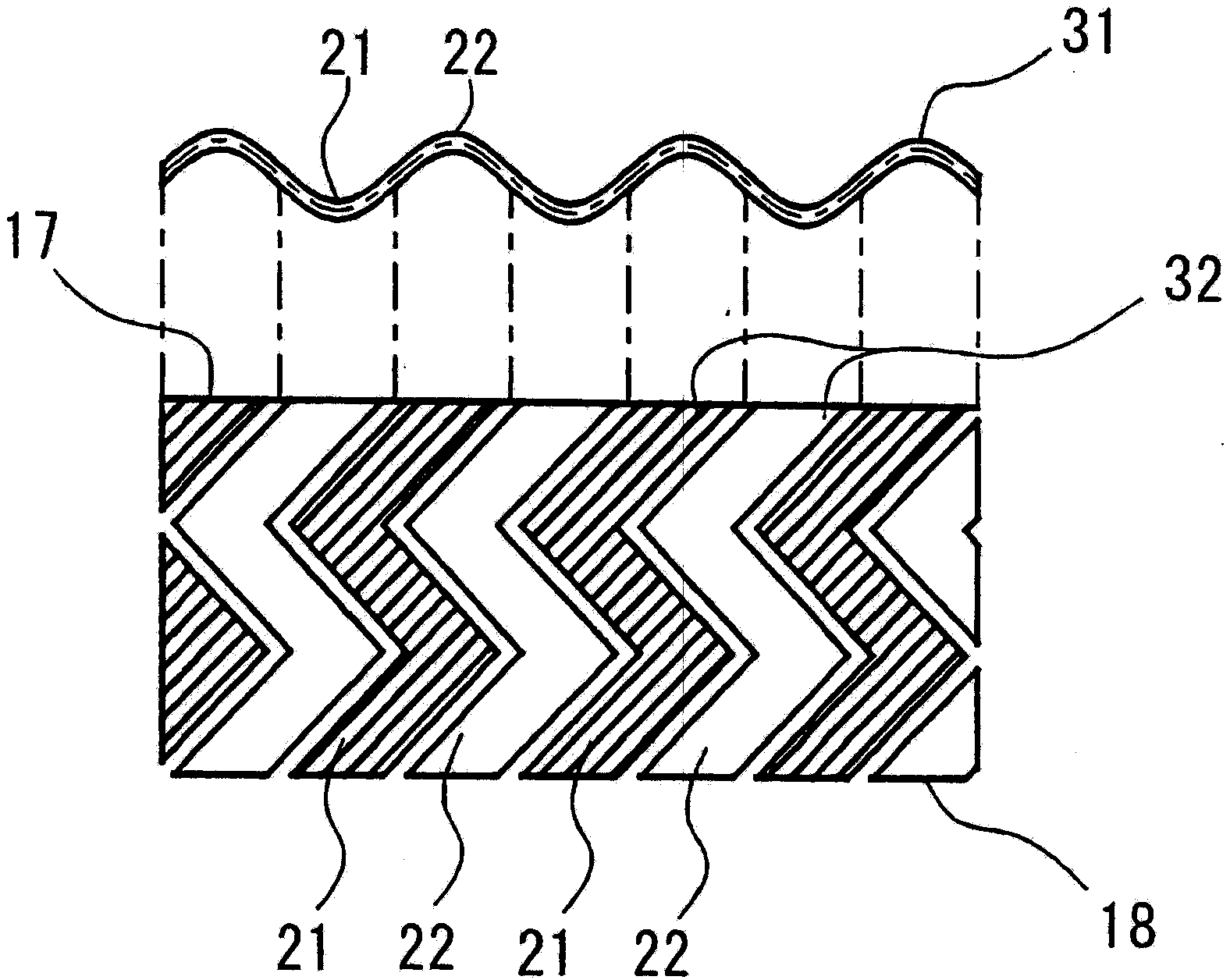
[0007] However, in the pneumatic tire of Patent Document 1, the zigzag shape of the peaks 21 and valleys 22 of the wave meander 31 extends to the meander bottom 18 even though the height of the lugs is low and the rigidity of the lugs is increased after the middle stage of wear.
As a result, the rigidity of the bump is extremely increased, and the moderate inversion of the bump does not occur, and the grounding performance is deteriorated, and the edge effect may become insufficient.
[0008] Also, when new, since the peaks 21 and valleys 22 of the zigzag extend obliquely from the tread surface 17, an acute-angled portion 32 is formed at the opening of the zigzag, so partial wear may also occur.

Method used


Image

  • Pneumatic tire
  • Pneumatic tire
  • Pneumatic tire

Examples


Embodiment

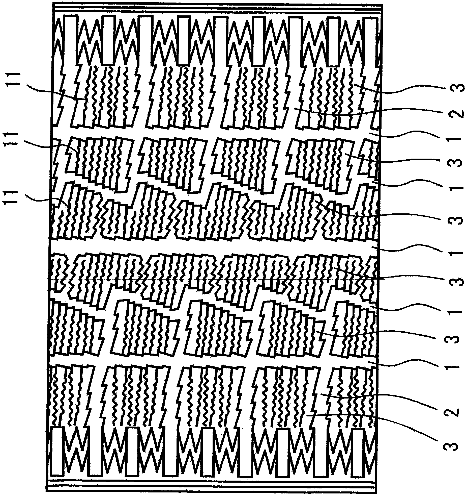
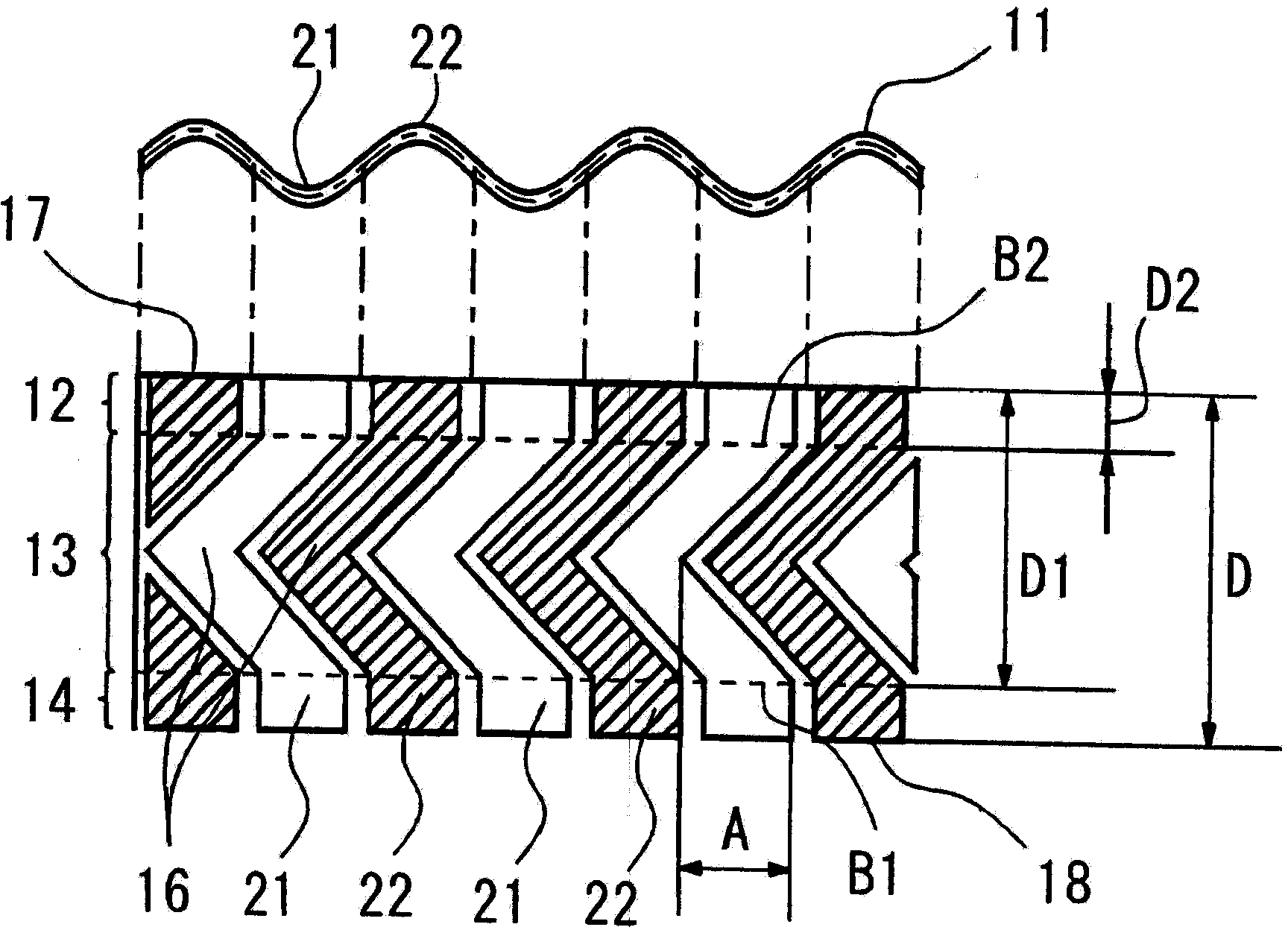
[0040] As an example, the pneumatic tire of the present invention and the pneumatic tire of the conventional example were tested and evaluated for performance. Any 1 tire has figure 1 The tread pattern shown, examples have figure 2 The zigzag pattern shown in the previous example has image 3 The zigzag pattern shown in . The depth D of any one zigzag pattern is 7 mm, and in the example, D1 is 5.5 mm, D2 is 1.5 mm, and A is 2 mm. The tire size is 195 / 65R15, and the performance is evaluated on a 2000ccFF van.

[0041] In Table 1, ice braking is the inverse of the ABS braking distance at a speed of 40 km / h on icy roads. The conventional tire when new is represented as an index of 100, and the larger the number, the better the performance. In addition, the term "wear time" refers to the time when the tread is worn to 60% of the zigzag depth D.

[0042] [Table 1]

[0043]

[0044] According to Table 1, since the peaks and valleys of the waveform are not zigzag, b...


PUM


Abstract

It is a subject to suitably decrease the rigidity of blocks, to generate suitable collapsing of the blocks, to sufficiently exhibit edge effects of sipes, and to improve braking performances and the like in the medium term of wear and thereafter; and for solving this subject, in a pneumatic tire formed with blocks on its tread and engraved with sipes 11 on the blocks, the sipes 11 are classified into a surface portion 12 , an intermediate portion 13 , and a bottom portion 14 in a depth direction from a tread surface 17 up to sipes bottom 18 , wherein the surface portion 12 and the bottom portion 14 open in a wave-shaped form in which crest portions 21 and trough portions 22 of the wave-shaped form extend in directions vertical to the tread, while the intermediate portion 13 opens in a wave-shaped manner in which the crest portions 21 and trough portions 22 of the wave-shaped form extend in a zigzag-like manner.

Description

[0001] This application is a divisional application of Chinese invention patent application No. 200510064921.5 filed on April 4, 2005 and entitled "Pneumatic Tire". technical field [0002] The present invention relates to a pneumatic tire in which zigzags (Japanese: サイプ) are engraved on bumps (Japanese: サイプ), and more particularly, to a pneumatic tire capable of improving tire performance while securing ground contact after the middle of tire wear. Background technique [0003] In pneumatic tires, circumferential grooves and lateral grooves are usually engraved on the tread surface, and in addition, zigzag grooves with a narrow width are engraved to improve drainage. In addition, more zigzags are engraved on the strutless tires intended for driving on icy and snowy roads, and the edge effect of the zigzags can be exerted to improve braking / driving performance and cornering performance. [0004] Generally, the rigidity of the bump is lowered due to the engraving of the zigza...

Claims


Application Information

Patent Timeline
Patent Type & Authority Applications(China)
IPC IPC(8): B60C11/113
CPCY10S152/03B60C2011/1213B60C11/124Y10S152/902B60C11/12B60C11/1218B60C2011/1338Y10T152/10
Inventor 大桥稔之
Owner TOYO TIRE & RUBBER CO LTD
Learn More