Door lock device for washing machine

A technology for washing machines and door locks, applied in washing devices, other washing machines, applications, etc., can solve problems such as bad influence of gears, and achieve the effect of reducing the range

Active Publication Date: 2016-08-10
SCD CO LTD
View PDF6 Cites 0 Cited by
  • Summary
  • Abstract
  • Description
  • Claims
  • Application Information

AI Technical Summary

Problems solved by technology

[0023] However, the above-mentioned washer-shaped leaf springs 41a, 41b have a problem of having a bad influence on the gears due to their large frictional force and the frictional force acting on the gears at the same time when sliding occurs.

Method used


Image

  • Door lock device for washing machine
  • Door lock device for washing machine
  • Door lock device for washing machine

Examples


Embodiment Construction

[0078] Preferred embodiments of the present invention will be described below with reference to the drawings, and the same reference numerals will be used for the same parts as conventional ones, and detailed descriptions will be omitted.

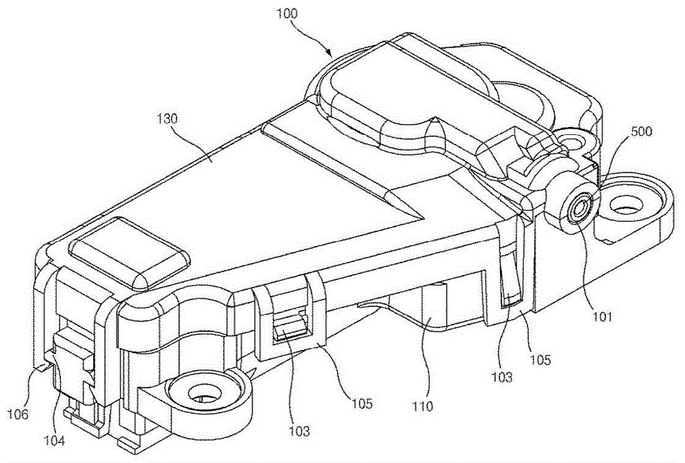
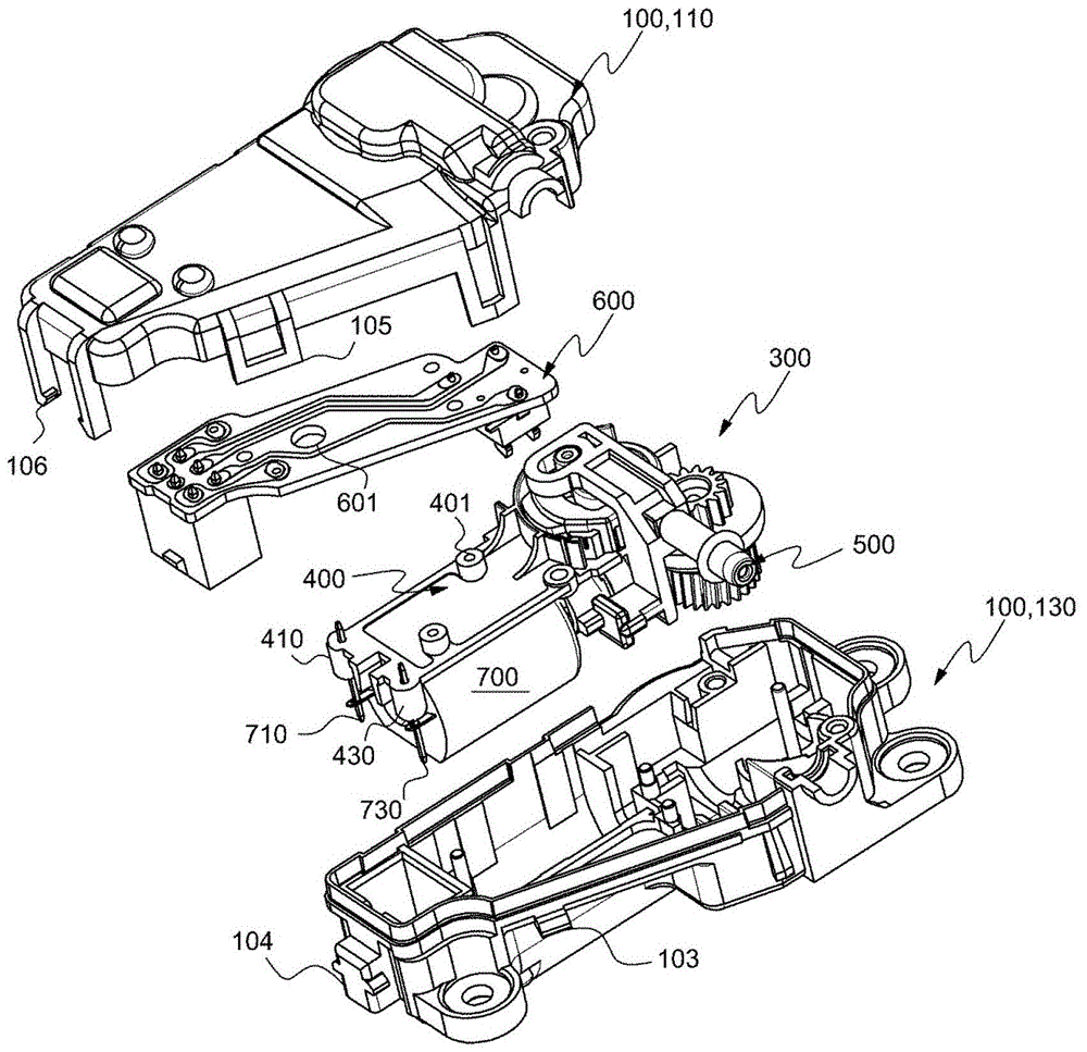
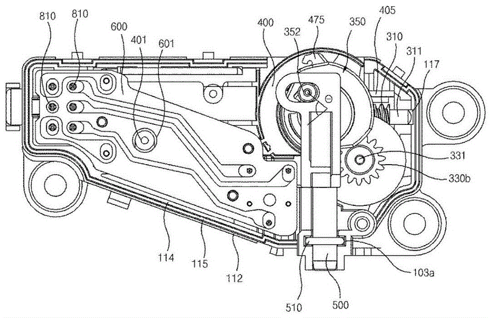
[0079] Such as Figure 1a and Figure 1b As shown, the door lock device for a washing machine according to this embodiment includes: a drive unit 300, mounted on the casing 100, to make the lock pin 500 move forward and backward, a motor 700, to provide power to the drive unit 300, and a printed circuit board 600, Connect with the motor 700 mentioned above.

[0080] At this time, the above-mentioned motor 700 and the printed circuit board 600 are disposed inside the above-mentioned housing 100 in the vertical direction, and the middle plate 400 is disposed between the above-mentioned motor 700 and the printed circuit board 600, so that the above-mentioned motor 700 and the printed circuit board 600 are respectively It is fixed on the uppe...


PUM


Abstract

The invention relates to a door locking apparatus for washing machines, wherein the door locking apparatus is installed on a washing machine body and is used for locking the state of a closed cover. The invention especially relates to a door locking apparatus for washing machines, wherein a printed circuit board (PCB) and a motor are respectively disposed on the top and the bottom of a immediate board in order to compress a size.

Description

technical field [0001] The present invention relates to a door lock device for a washing machine which is mounted on the main body of the washing machine to lock the closed state of the lid. In particular, it relates to a door for a washing machine whose size is reduced by arranging a printed circuit board (PCB) and a motor above and below an intermediate plate. lock device. Background technique [0002] Such as Figure 14 and Figure 16 As shown, the conventional door lock device for a washing machine includes: a casing 10 forming an external shape; a drive unit 30 mounted inside the above-mentioned casing 10; to move forward and backward. [0003] The above-mentioned opening 11 is formed into a circle by combining the case 10A and the cover 10B, each having a semicircular shape, and the lock pin 50 is slidably guided through the opening 11 . [0004] On the other hand, the above-mentioned opening 11 is provided with an O-ring 12 to perform a sealing function to prevent ...

Claims


Application Information

Patent Timeline
Patent Type & Authority Patents(China)
IPC IPC(8): D06F37/28D06F39/14
Inventor 崔宰馨
Owner SCD CO LTD
Why Eureka
Try Eureka