Supercharge Your Innovation With Domain-Expert AI Agents!

Combined wire binding device

A cable tie and combined technology, which is applied in the direction of building types, cable installation devices, electrical components, etc., can solve the problems of short service life and easy corrosion of the cable, and achieve the effect of convenient operation, convenient portability and long service life

Active Publication Date: 2015-05-27
STATE GRID CORP OF CHINA +1
View PDF6 Cites 0 Cited by
  • Summary
  • Abstract
  • Description
  • Claims
  • Application Information

AI Technical Summary

Problems solved by technology

[0004] In order to overcome the technical defects of easy corrosion and short service life caused by manual cable winding in the existing method, the invention discloses a combined cable tie

Method used


Image

  • Combined wire binding device

Examples


Embodiment Construction

[0014] The specific embodiment of the present invention will be further described in detail below in conjunction with the accompanying drawings.

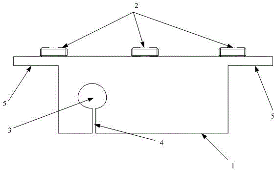
[0015] The combined wire binding device of the present invention includes an operating lever and a binding plate 1, a lead hole 3 is opened on the binding plate, and a lead groove 4 is opened from the lead hole 3 to the edge of the binding plate, and the binding plate An operating rod sleeve 2 is also fixed on the edge, and the inner diameter of the operating rod sleeve is greater than the outer diameter of the operating rod.

[0016] During use, the operating rod is passed through the operating rod sleeve 2, and the binding plate and the operating rod are fixed together by the operating rod sleeve. The lead wire is snapped into the lead wire hole of the wire tie plate from the lead wire slot, and after the wire tie is made, the end of the wire tie is sealed by the wire tie plate.

[0017] Using the combined wire tie device of the ...


PUM


Abstract

The invention relates to a combined wire binding device, comprising an operating rod and a wire binding plate, wherein a wire leading hole is formed in the wire binding plate, a wire leading slot is formed from the wire leading hole to the edge of the wire binding plate, the edge of the wire binding device is fixedly provided with an operating rod sleeve, and the inner diameter of the operating rod sleeve is larger than the external diameter of operating rod. By adopting the combined wire binding device, the wire binding plate can be separated from the operating rod, the combined wire binding device is convenient to carry, and the operation is more laboursaving; the combined wire binding device can bear sufficient strength and cannot be deformed in an operating process; and meanwhile, the service life of a bracing wire is prolonged, time and labour are saved, operation is convenient, and the manufacturing process of a bundle is better.

Description

technical field [0001] The invention belongs to the field of electric equipment, and relates to a combined wire binder. Background technique [0002] Pull wires are commonly used in tension rods, corner rods and other places of power distribution lines. The use of pull wires is selected according to the wire diameter and stress of the line. The commonly used types of pull wires are GJ-50, GJ-70, GJ-100 and other models. After the guy wire is finished, when the staff seals the tail end of the guy wire, they use iron wire to wind the tail end of the guy wire. [0003] Due to the manual operation, the galvanized layer on the surface of the iron wire is often damaged when winding the end of the cable. In areas with high air humidity or salinity, it is easy to cause the rust at the connection between the iron wire and the end of the cable to accelerate, and the service life of the cable Not more than 2 years. When encountering strong winds and heavy rains, it is easy to affect ...

Claims


Application Information

Patent Timeline
Patent Type & Authority Patents(China)
IPC IPC(8): E04H12/20H02G1/00
Inventor 赵强
Owner STATE GRID CORP OF CHINA
Features
  • R&D
  • Intellectual Property
  • Life Sciences
  • Materials
  • Tech Scout
  • Unparalleled Data Quality
  • Higher Quality Content
  • 60% Fewer Hallucinations
Learn More