cam follower
A cam follower, sliding cam technology, applied in the direction of engine components, transmissions, machines/engines, etc., can solve problems such as huge purchase and manufacturing costs, and achieve the effect of good guidance
- Summary
- Abstract
- Description
- Claims
- Application Information
AI Technical Summary
Problems solved by technology
Method used
Image
Examples
Embodiment Construction
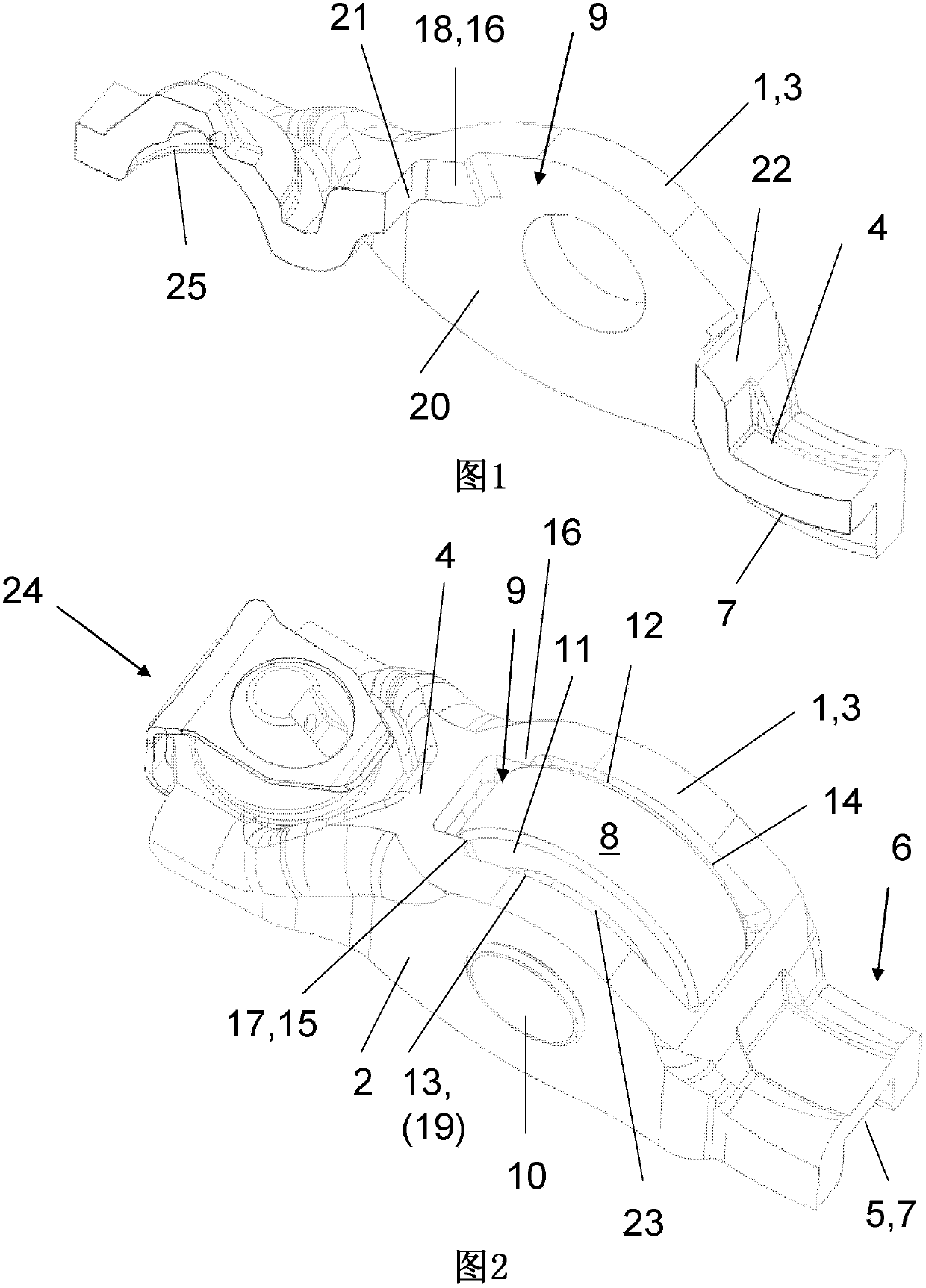
[0017] A cam follower 1 is shown as a sheet metal drawbar for a valve drive of an internal combustion engine. The cam follower has two substantially vertical side walls 2 , 3 which are connected by an upper crosspiece 4 such that an inverted U-shaped profile is formed in cross section.
[0018] On the underside 5 of the crosspiece 4 a device 7 for a ventilation valve is applied at one end 6 . On the other end 24 of the crosspiece 4 , on the underside 5 , a spherical segment-shaped contact surface 25 for the support element is shown.
[0019] The crosspiece 4 has a rectangular frame-like recess 9 penetrated by a roller 8 . The roller 8 is used for camming and in this case runs on a pin 10 placed in the side walls 2 , 3 via a bearing 23 . as by figure 2 As can be seen, a needle bearing arrangement is provided as bearing means 23 which extends with a slight axial play directly in front of the inner surfaces 19 , 20 of the side walls 2 , 3 . It can also be seen that the side ...
PUM
 Abstract
Description
Claims
Application Information
 - R&D
- Intellectual Property
- Life Sciences
- Materials
- Tech Scout
- Unparalleled Data Quality
- Higher Quality Content
- 60% Fewer Hallucinations
Browse by: Latest US Patents, China's latest patents, Technical Efficacy Thesaurus, Application Domain, Technology Topic, Popular Technical Reports.
© 2025 PatSnap. All rights reserved.Legal|Privacy policy|Modern Slavery Act Transparency Statement|Sitemap|About US| Contact US: help@patsnap.com

