
Eureka
For R&D, Eureka makes reading and utilizing patents & technical documents easy.
Eureka AIR
Designed for self-driven R&D workflows. Generate viable solutions, solve complex R&D challenges, empower your innovation with AI.

Eureka Materials
Designed for material experts only. Revolutionize your material R&D, from search, analyze, to developing new materials.

TechResearch
Generate reliable direction feasibility study reports for your R&D in just a few steps.

TechSeek
Discover and master advanced knowledge NOW. Basics, ideas, possibilities, all at once.

TechMind
As an expert in R&D Theories, TechMind can generates customized viable solutions instantly.

TechRisk
Analyze your overall solution with one click, know your potential R&D risks in advance.

TechMonitor
Get weekly tech updates, stay abreast of the latest tech innovations and key insights.
Magnetic refrigeration device and magnetic refrigeration system
A magnetic refrigeration and equipment technology, applied in refrigeration and liquefaction, refrigerators, lighting and heating equipment, etc., can solve problems such as high hydraulic loss and lower refrigeration efficiency
- Summary
- Abstract
- Description
- Claims
- Application Information
AI Technical Summary
Problems solved by technology
Method used
Image

Examples
no. 1 example )
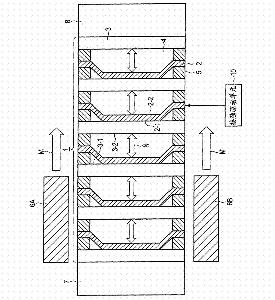
[0043] figure 1 A magnetic refrigeration system according to a first embodiment is shown. The magnetic refrigeration system includes a magnetic refrigeration device 1 . The magnetic refrigeration device 1 has a structure in which a plurality of plate-shaped solid heat storage members 3 having a heat storage function and formed rigidly are arranged in parallel to each other. A solid thermal storage member 3 is provided as a fixed member. Spaces 4 are defined between respective adjacent pairs of solid heat storage members. The plate-shaped magnets 2 having a magnetocaloric effect and being flexible are provided in spaces 4 defined between respective adjacent pairs of solid heat storage members 3 and are arranged in parallel to each other. The magnet 2 is provided as a movable member. The magnet may be brought into thermal contact with the adjacent solid heat storage member 3 . Solid heat storage members 3 and magnets 2 are arranged alternately. Spacers 5 defining a space 4...
no. 2 example )
[0065] refer to Figure 4 , a magnetic refrigeration system according to a second embodiment will be described. exist Figure 4 In the magnetic refrigeration system shown, each magnet 2 (movable member) in the magnetic refrigeration device 1 is held away from the corresponding one of the solid thermal storage members 3 and is attracted by a magnetic force applied by an external magnetic field. The force remains in contact with another solid thermal storage member 3 (fixed member). That is, the switching of the pair of magnetic members is achieved by the driving force based on the magnetic attraction force applied by the external magnetic field.
[0066] included in Figure 4 In the magnetic refrigeration device 1 in the magnetic refrigeration system of the shown second embodiment, the magnet 2 is constructed as a movable member. Application and removal of a magnetic field to and from the magnet 2 is achieved by moving the magnetic field applying units 6A and 6B, whereby th...
no. 3 example )
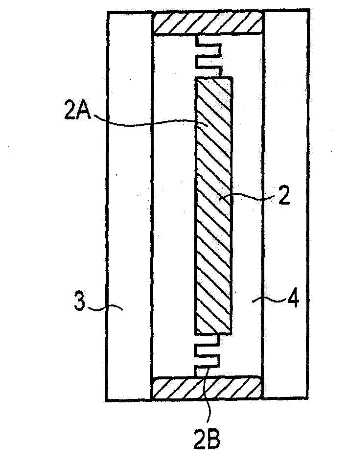
[0068] refer to Figure 5 , a magnetic refrigeration system according to a third embodiment will be described. included in Figure 5 In the magnetic refrigeration device 1 in the magnetic refrigeration system shown, the force for driving the magnet 2 (movable member) is provided as an electrostatic force, thereby switching between two solid thermal storage members 3 with which the magnet 2 is in contact. Solid thermal storage member 3 (fixed member).
[0069] Figure 5 The unit structure of the magnetic refrigeration device 1 is shown. In this device, it is sufficient that the magnet 2 or the solid heat storage member 3 is provided as the movable member. exist Figure 5 In the second embodiment shown, the magnet 2 is provided as a movable member. A voltage for generating an electrostatic force therebetween is applied between the magnet 2 and each of the solid heat storage members 3A and 3B. The solid thermal storage members 3A and 3B are composed of an electrically cond...
PUM
 Abstract
Description
Claims
Application Information
 - R&D Engineer
- R&D Manager
- IP Professional
- Industry Leading Data Capabilities
- Powerful AI technology
- Patent DNA Extraction
Browse by: Latest US Patents, China's latest patents, Technical Efficacy Thesaurus, Application Domain, Technology Topic, Popular Technical Reports.
© 2024 PatSnap. All rights reserved.Legal|Privacy policy|Modern Slavery Act Transparency Statement|Sitemap|About US| Contact US: help@patsnap.com