Plate heat exchanger with several modules connected by plate strips

A plate heat exchanger and heat exchange medium technology, applied in the direction of heat exchanger fixation, indirect heat exchanger, heat exchange equipment, etc., to achieve the effect of improving thermal connection, mechanical connection and thermal contact

Active Publication Date: 2016-11-23
LINDE AG
View PDF9 Cites 0 Cited by
  • Summary
  • Abstract
  • Description
  • Claims
  • Application Information

AI Technical Summary

Problems solved by technology

However, process requirements often require larger heat exchange surfaces and thus larger heat exchanger blocks

Method used


Image

  • Plate heat exchanger with several modules connected by plate strips
  • Plate heat exchanger with several modules connected by plate strips
  • Plate heat exchanger with several modules connected by plate strips

Examples


Embodiment Construction

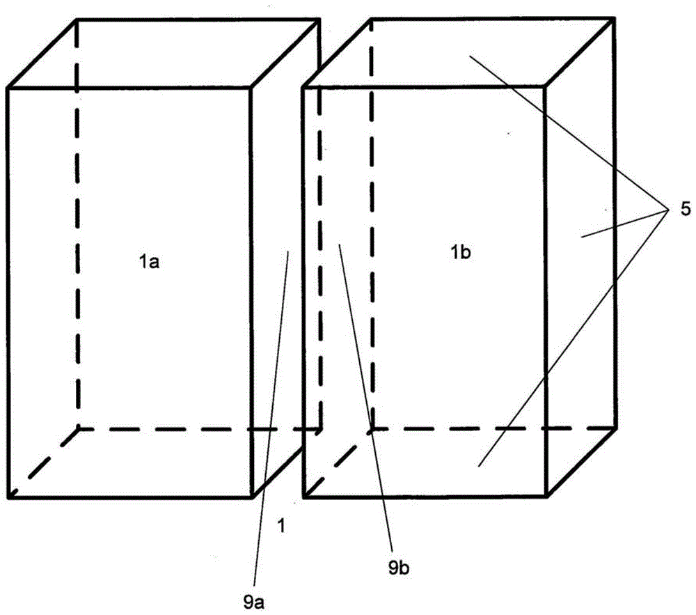
[0033] figure 2 The solution of a plate heat exchanger 1 according to the invention shown in , comprises two modules 1a and 1b. The two modules 1 a and 1 b are rectangular parallelepiped-shaped and are each closed to the outside by a cover 5 . The two modules 1a and 1b are arranged such that cover sheets 9a and 9b correspondingly of the same size are directly adjacent. The two cover sheets 9 a and 9 b form the contact surface between the two modules 1 a and 1 b of the plate heat exchanger 1 . The two contact surfaces 9a and 9b are connected to one another by a suitable adhesive.

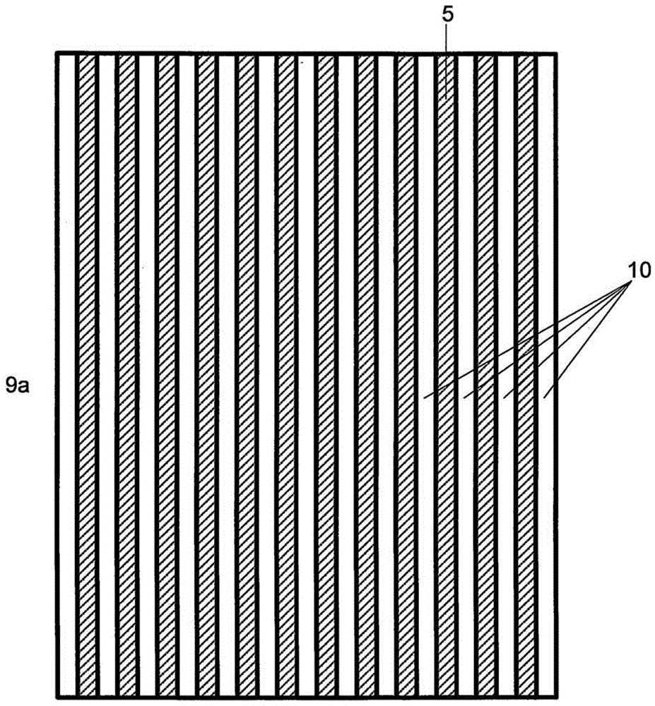
[0034] exist image 3 Details are shown in . exist image 3 The contact surface 9a is shown in . The cover sheet 5 (shown hatched) is provided with adhesive. A plurality of sheet metal strips 10 are connected to the contact surface 9a by means of an adhesive. The sheet metal strip 10 has a length corresponding to the edge length of the cover sheet 9a. The sheet metal strips 10 are arranged ...


PUM


Abstract

The heat exchanger (1) has modules (1a,1b) that are arranged next to one another such that contact surface (9a) of cuboidal module (1a) is arranged adjacent to contact surface (9b) of cuboidal module (1b). The fittings are provided for supplying and discharging heat-exchanging media. The headers are provided for distributing and collecting heat-exchanging media to and / or form the passages. The adjacent sides of modules are covered by the cover sheets (5). The contact surfaces of the modules are joined with one another through adhesive. An independent claim is included for method for producing plate heat exchanger.

Description

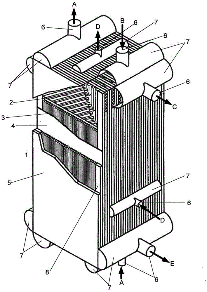
technical field [0001] The invention relates to a plate heat exchanger and a method for manufacturing the same, the plate heat exchanger comprising: [0002] at least two modules, each of which has a plurality of channels arranged in a stack, through which the heat exchange medium can alternately flow and which are separated from one another by webs; [0003] The modules are rectangular parallelepiped as a whole and are delimited on the outside by covers; [0004] the modules are arranged side by side in such a way that a rectangular side of one rectangular parallelepiped-shaped module directly adjoins a corresponding rectangular side of another rectangular parallelepiped-shaped module; [0005] the modules have means for input and output of heat exchange medium and means for distribution of heat exchange medium onto and collection of heat exchange medium from individual channels (Headers); and [0006] • wherein at least two modules have at least one common header. Backgr...

Claims


Application Information

Patent Timeline
Patent Type & Authority Patents(China)
IPC IPC(8): F28D9/00
CPCF25J3/04236F25J5/002F25J2290/32F25J2290/42F25J2290/50F28D9/0068F28F2275/025Y10T29/49366B23P15/26F28D9/0062F28F3/08F28F3/086F28F9/26
Inventor J·迪特里希R·赫茨尔
Owner LINDE AG
Why Eureka
Try Eureka