Motion position detection mechanism and X-ray imaging device

A technology for detecting mechanism and motion position, applied in photography, measuring device, optics, etc., can solve the problems of complex overall structure and rising cost.

Active Publication Date: 2013-10-23
SHENZHEN MINDRAY BIO MEDICAL ELECTRONICS CO LTD
View PDF7 Cites 2 Cited by
  • Summary
  • Abstract
  • Description
  • Claims
  • Application Information

AI Technical Summary

Problems solved by technology

Moreover, the components of these transmission mechanisms require relatively precise equipment for processing, and for those non-

Method used


Image

  • Motion position detection mechanism and X-ray imaging device
  • Motion position detection mechanism and X-ray imaging device
  • Motion position detection mechanism and X-ray imaging device

Examples


Embodiment Construction

[0019] The present invention will be further described in detail below through specific embodiments in conjunction with the accompanying drawings.

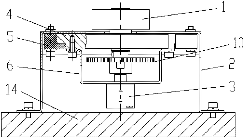
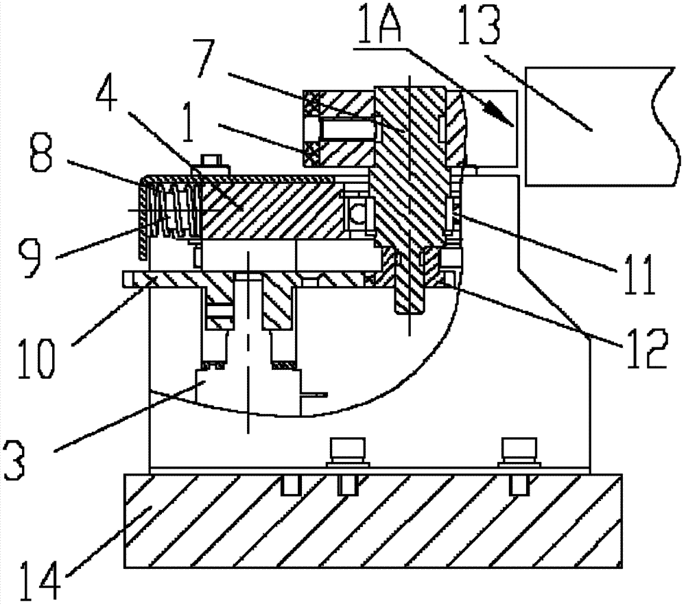
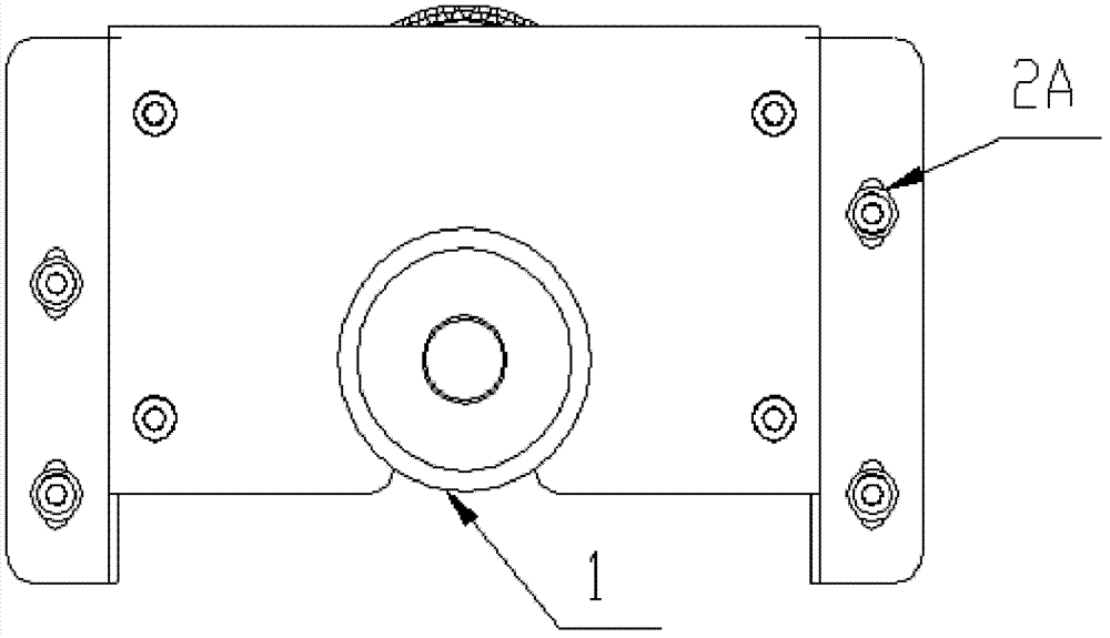
[0020] The motion position detection mechanism in the embodiment of the present application uses the rolling friction force during motion to directly drive the roller to rotate to detect the motion position of the moving part. When the moving part is moving, a roller fixed on the motion position detection mechanism will Rotate, and convert the rotation of the roller to the position sensor to detect the movement position. The motion position detection mechanism in the embodiment of the present application includes a fixed frame, a roller shaft, a roller and a position sensor. The fixed frame is fixed on one of the moving parts and the walking track; the roller rotating shaft is rotatably fixed on the fixing frame; The surface of one is in contact, and when the moving part moves, friction is generated on the contact surface of the ...


PUM


Abstract

The invention discloses a motion position detection mechanism including a fixed frame for being fixed on either one of a moving part and a moving track; a roller rotating shaft which is fixed on the fixed frame in a rotatable way; a roller which is fixed on the roller rotating shaft; and a position sensor which is connected with the roller rotating shaft and rotates under the drive of the roller rotating shaft and outputs a position signal of the moving part. And the surface of the roller is used for contacting the surface of the other of the moving part and the moving track; when the moving part moves, friction is generated on the contact surfaces of the roller and the other of the moving part and the moving track; and the roller rolls under the action of the friction and drives the roller rotating shaft to rotate. The invention also discloses the X-ray imaging device. The motion position detection mechanism makes use of the rolling friction when the moving part moves so that the roller which is fixed on the position detection mechanism is capable of rotating, and then the rotation of the roller is transmitted to the position sensor so that position detection of the moving part is realized.

Description

technical field [0001] The invention relates to a movement position detection mechanism and an X-ray imaging device adopting the movement position detection mechanism. Background technique [0002] On some devices, some parts need to be moved manually, and the moving position of the moving part needs to be known, so the moving position of the moving part needs to be detected. Most of the position detection methods of moving parts currently used in some non-precision positioning equipment are to transmit the movement stroke of the moving parts to the movement position detection mechanism through some meshing transmission mechanisms, and finally to the position sensor. When this method of detecting the moving position of the moving part is adopted, there is a motion transmission between the moving position detection mechanism and the walking track of the moving part, which requires the existence of a transmission mechanism, that is, the contact surface of the two needs to be d...

Claims


Application Information

Patent Timeline
IPC IPC(8): G01B21/00G03B42/02
Inventor 王元黄善志
Owner SHENZHEN MINDRAY BIO MEDICAL ELECTRONICS CO LTD
Why Eureka
Try Eureka