Rotor position detection method of brushless DC motor based on single-phase inductance detection

A technology for rotor position detection and brushing of DC motors, applied in AC motor control, electronic commutation motor control, motor control and other directions, can solve the problem that the detection vector has no driving effect, the motor speed and torque performance are poor, and the detection accuracy is reduced. and other problems, to achieve the effect of improving the driving effect, reducing the flow of reactive energy, and reducing the torque ripple

Inactive Publication Date: 2020-09-29
天津卓业科技发展有限公司
View PDF3 Cites 0 Cited by
  • Summary
  • Abstract
  • Description
  • Claims
  • Application Information

AI Technical Summary

Problems solved by technology

The rotor position detection method based on the inductance method needs to inject the detection vector pulse, and the detection vector often has no driving effect or the driving effect is very poor, resulting in relatively poor performance of the motor speed and torque using this method; and the addition of the detection vector is prolonged. The control cycle is shortened, so that the detection accuracy will decrease with the increase of the motor speed

Method used


Image

  • Rotor position detection method of brushless DC motor based on single-phase inductance detection
  • Rotor position detection method of brushless DC motor based on single-phase inductance detection
  • Rotor position detection method of brushless DC motor based on single-phase inductance detection

Examples


Embodiment Construction

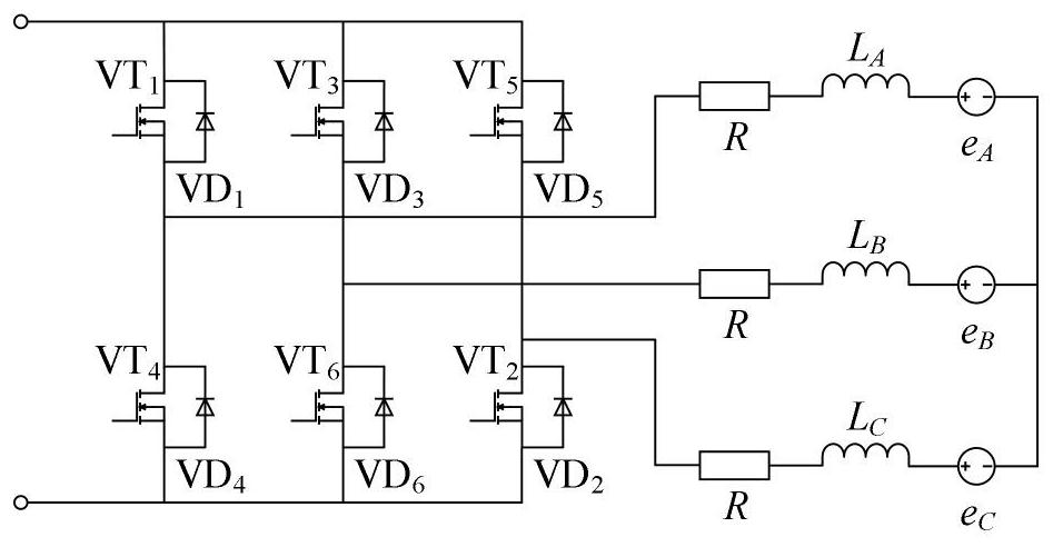
[0033] Three-phase inverter circuit diagram of brushless DC motor figure 1 As shown, the three-phase voltage equation is

[0034]

[0035] In the formula: U A , U B , U C Respectively A, B, C phase terminal voltage; i A i B i C Respectively A, B, C phase phase current; e A 、e B 、e C Respectively A, B, C opposite electromotive force; R is the winding resistance; L A , L B , L C is the equivalent inductance of A, B, and C phase windings; U N is the voltage from the neutral point of the motor to ground.

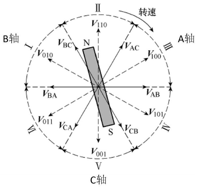
[0036] The voltage vector application method of each sector is shown in Table 1, and the principle of the detection method of the present invention is introduced by taking sector III as an example.

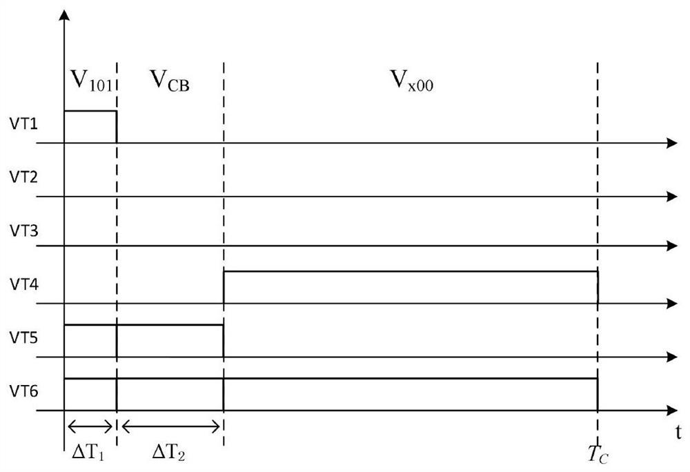
[0037] image 3 is the voltage vector application method in the control period of sector III, V 101 , V CB , V x00 The three voltage vectors divide the control cycle into three phases.

[0038] Phase one:

[0039] Apply three-phase voltage vector V 101 , then ...


PUM


Abstract

The invention relates to a brushless direct current motor rotor position detection method based on single-phase inductance detection. The brushless direct current motor rotor position detection methodincludes the following steps that a detection vector with the time duration being delta T1 is applied to a motor stator winding, the detection phase current is sampled at the beginning and end of vector application correspondingly, and the current change rate is obtained through subtraction of two values; a driving vector with the time duration being delta T2 is applied to the motor stator winding to drive a motor to run; induction energy is released slowly and the motor driving current is maintained by applying a circulation follow current vector in the remaining time of the control period;the variation trend of frac{d}{d<t>} is judged; and the execution steps are repeated continuously after a motor rotor passes through a switching point, and the motor rotor is switched to the next section after waiting for a delay at an electrical angle of 30 degrees.

Description

technical field [0001] The invention belongs to the technical field of motor control, and in particular relates to a method for detecting the rotor position of a brushless DC motor. Background technique [0002] Brushless DC motors have been widely used because of their simple structure, high operating efficiency, and convenient maintenance. Traditional brushless DC motors generally use three-phase six-state two-two conduction mode for drive control, and the rotor position sensor is required to detect six rotor position signals in one electrical cycle in order to commutate the windings. However, the installation of the rotor position sensor increases the size and cost of the motor, and the sensor signal is susceptible to environmental electromagnetic signal interference, which reduces the reliability of the system. Therefore, the research on sensorless rotor position detection technology has important theoretical research significance and application value. [0003] At pres...

Claims


Application Information

Patent Timeline
Patent Type & Authority Patents(China)
IPC IPC(8): H02P6/185H02P27/12H02P6/10
CPCH02P6/10H02P6/185H02P27/12H02P2207/05
Inventor 方红伟陈奇李国平
Owner 天津卓业科技发展有限公司
Why Eureka
Try Eureka