A material conveying and automatic loading and unloading system for main bearing cap processing

A technology of automatic loading and unloading and main bearing cap, which is applied in metal processing and other directions, can solve the problems of low manual loading and unloading efficiency, affecting processing efficiency, and high labor intensity, so as to improve processing production efficiency, reduce labor intensity, and improve The effect of work efficiency

Active Publication Date: 2020-08-18
XY HUST ADVANCED MFG ENG RES INST +1
View PDF6 Cites 0 Cited by
  • Summary
  • Abstract
  • Description
  • Claims
  • Application Information

AI Technical Summary

Problems solved by technology

The conveying system of the prior art has the following defects: low efficiency. In order to improve the conveying efficiency of workpieces in the existing conveying lines, generally a plurality of conveying lines are arranged side by side, and manual loading and unloading is adopted, and the efficiency of manual loading and unloading is low. And there needs to be room between the conveyor lines for workers to enter and exit, and in the actual operation process, the workers at the internal conveyor line are limited by the space, so the operation is very inconvenient, and if the distance between the conveyor lines is increased blindly, it will Occupying too much space makes the structure not compact enough, which also affects the subsequent processing efficiency, and if all the conveying lines are changed to automatic production lines, the cost will be high, and it is not suitable for the reconstruction of the factory production line with limited budget; the manual loading and unloading Generally, workers take off the semi-finished products from the conveyor line and put them on the machine tool for processing. After the processing is completed, they take off the finished product and put it on the finished product conveyor line. The front and back of the workpiece directly affect the subsequent processing of the machine tool. , need manpower to judge the front and back of the workpiece, and then carry out the loading operation according to the front and back of the workpiece, the labor intensity of manpower is high, and the efficiency is relatively low

Method used


Image

  • A material conveying and automatic loading and unloading system for main bearing cap processing
  • A material conveying and automatic loading and unloading system for main bearing cap processing
  • A material conveying and automatic loading and unloading system for main bearing cap processing

Examples


Embodiment Construction

[0038] The present invention will be further described in conjunction with the accompanying drawings and specific embodiments. It should be understood that these examples are only used to illustrate the present invention and are not intended to limit the scope of the present invention. In addition, it should be understood that after reading the content taught by the present invention, those skilled in the art may make various changes or modifications to the present invention, and these equivalent forms also fall within the scope defined in the present application.

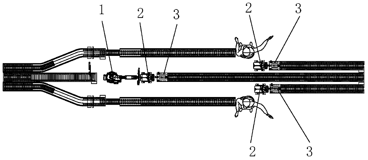
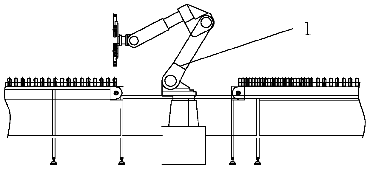
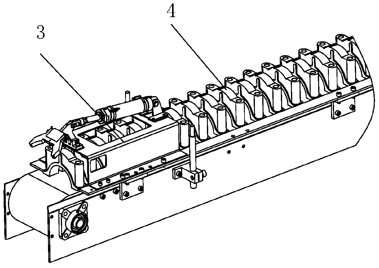
[0039] Such as Figure 1-15 As shown, it is a material conveying and automatic loading and unloading system for the main bearing cap processing provided by the present invention, which is used for the automatic processing production line of the main bearing cap inner cold drilling equipment. In the present embodiment, workpiece 4 is 5309323 ( Figure 14 , Figure 15 Shown) the engine main bearing cap as an examp...


PUM


Abstract

The invention provides a material conveying and automatic feeding and discharging system for processing a main bearing cap. The material conveying and automatic feeding and discharging system comprises three station conveying lines arranged in parallel; the station conveying line in the middle is a manipulator automatic feeding and discharging conveying line; the two station conveying lines positioned on the two sides are manual feeding and discharging conveying lines; a robot station is arranged on the manipulator automatic feeding and discharging conveying line; an automatic feeding and discharging robot is arranged at the robot station; manual operating stations are correspondingly arranged on the two manual feeding and discharging conveying lines; and front side and back side detectionthree-dimensional turntables are separately corresponding to the robot manual feeding and discharging conveying line on one side of the robot station and corresponding to the two manual feeding and discharging conveying lines on sides of the two manual operating stations. Through the reasonable layout of the conveying lines, the way of cooperation of the robot automatic conveying line and the manual conveying lines is adopted, so that on one hand, the operation convenience can be ensured, on the other hand, on the premise of controlling the cost, the processing and production efficiency of the engine main bearing cap is effectively improved.

Description

technical field [0001] The invention mainly relates to the technical field related to the processing and production of main bearing caps of engines, in particular to a material conveying and automatic loading and unloading system for processing main bearing caps. Background technique [0002] The main bearing cap of the engine is an important part of the engine. During the batch processing and production of the main bearing cap, the main bearing cap is generally cast into a semi-finished product, and then transported to the machine tool for fine processing through the corresponding conveyor line. [0003] In the prior art, the production line for batch conveying of the main bearing caps generally adopts a conveying chain, and the main bearing caps are placed on the conveying chain to realize conveying. The conveying system of the prior art has the following defects: low efficiency, in order to improve the conveying efficiency of workpieces in the existing conveying line, gen...

Claims


Application Information

Patent Timeline
Patent Type & Authority Patents(China)
IPC IPC(8): B23Q7/04
CPCB23Q7/04
Inventor 李波但雅波向华
Owner XY HUST ADVANCED MFG ENG RES INST
Why Eureka
Try Eureka