Combined-type material clamp

A combined and material technology, applied in the direction of analyzing materials, measuring devices, instruments, etc., can solve the problems of inability to clamp materials, poor universality of fixtures, and inability to adjust angles, etc., to achieve the effect of convenient operation, accurate response, and strong versatility

Active Publication Date: 2013-10-23
SOUTH CHINA AGRI UNIV
View PDF3 Cites 6 Cited by
  • Summary
  • Abstract
  • Description
  • Claims
  • Application Information

AI Technical Summary

Problems solved by technology

Since the angles of the existing disc-plate compression fixtures and 90° V-block fixtures cannot be adjusted, these two fixtures cannot clamp most materials
If it is necessary to test the above-mentioned materials with different shapes, it is necessary to remake special fixtures corresponding to the shape of the materials, resulting in long testing time and high costs.
Since each fixture is designed for different materials, the versatility of the fixture is poor

Method used


Image

  • Combined-type material clamp
  • Combined-type material clamp
  • Combined-type material clamp

Examples


Embodiment 1

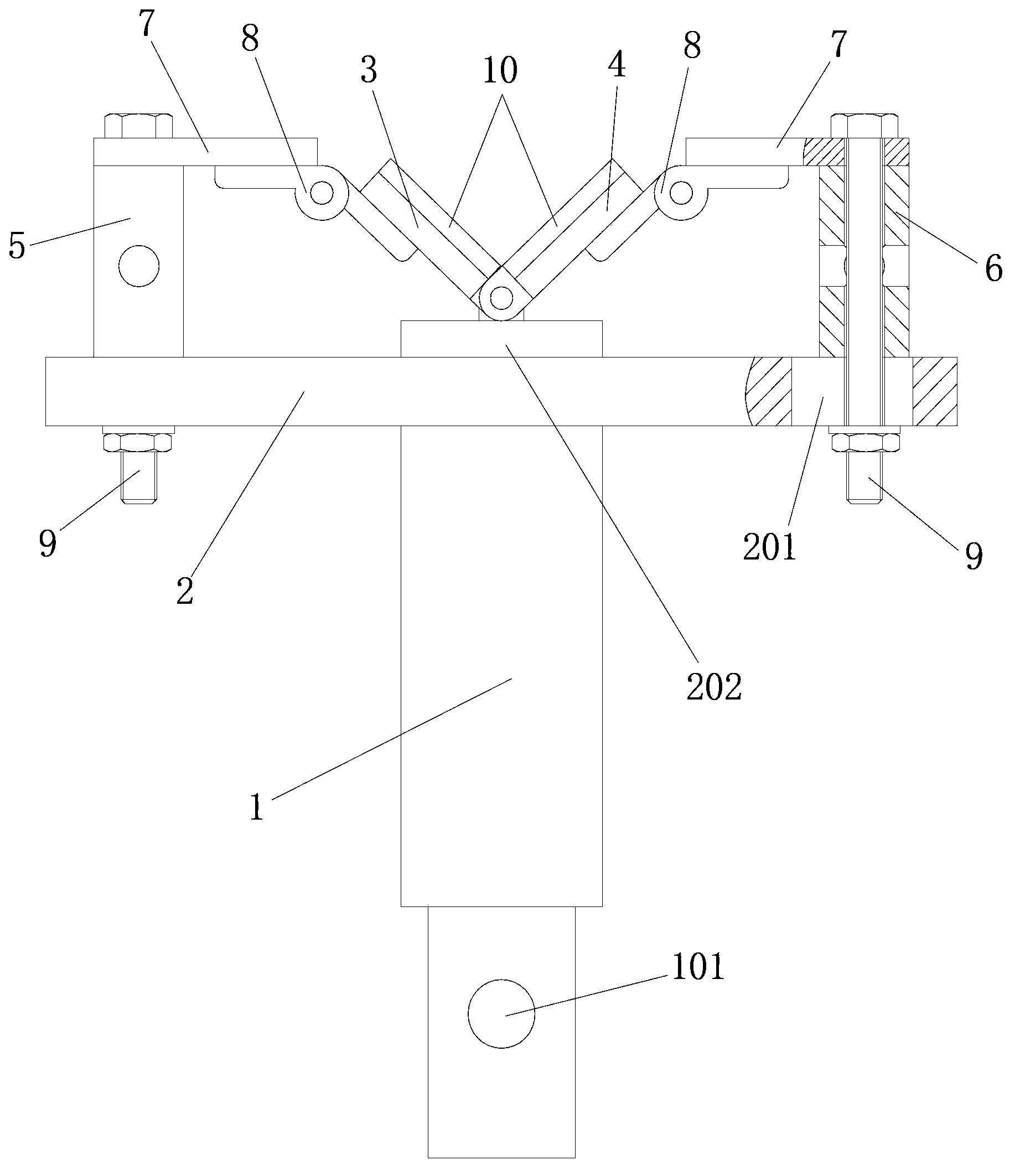
[0026] like figure 1 A combined material clamp is shown, the clamp device includes a connecting shaft 1, a supporting plate 2, a first clamping plate 3 and a second clamping plate 4, the supporting plate 2 is installed on one end of the connecting shaft 1, and the supporting plate The two ends of 2 are respectively provided with a first spacer 5 and a second spacer 6, one end of the first splint 3 is connected to the first spacer 5, and the other end is hinged to the middle part of the support plate 2; One end of the splint 4 is connected to the second spacer 6 , and the other end is hinged to the middle of the support plate 2 , while the other end of the first splint 3 is hinged to the other end of the second splint 4 . In order to facilitate the installation of the combined material fixture on the compression universal testing machine, the other end of the connecting shaft 1 is provided with a mounting hole 101 matched with the compression universal testing machine.

[0027...

Embodiment 2

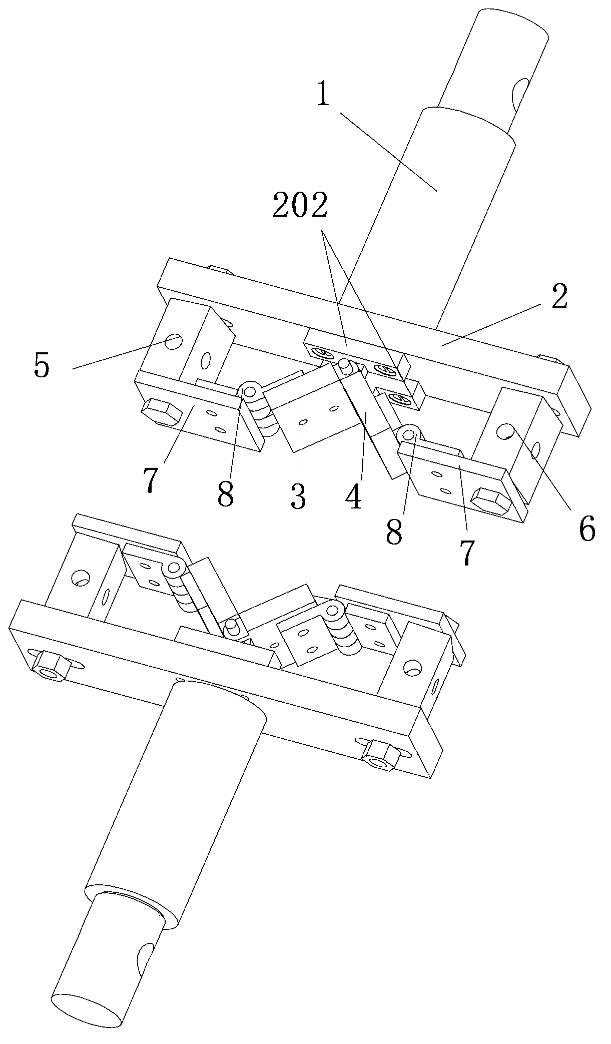
[0035] This combined material fixture is the same as embodiment 1 except the following technical features: as figure 2 As shown, the number of the combined material clamps is 2. When there are 2 combined material fixtures, the 2 combined material fixtures are respectively installed on the upper end and the lower end of the compression universal testing machine, and the lower end of the material to be tested is placed on the carrier 10 in the combined material fixture below. , and the upper end of the material to be tested is supported by the applicator 10 in the upper combined material clamp, so that through the cooperation of the two combined material clamps, the material to be tested is clamped.

Embodiment 3

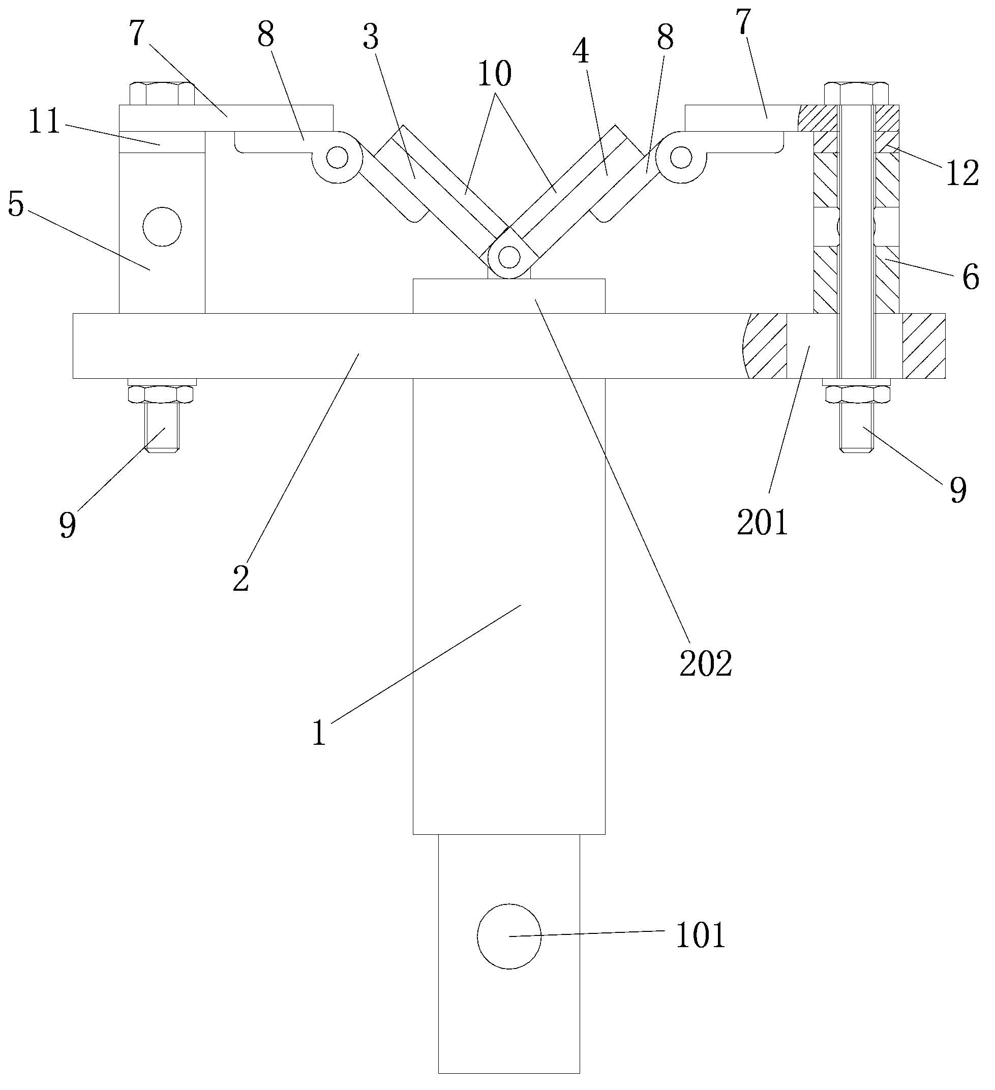
[0037] This combined material fixture is the same as embodiment 1 except the following technical features: as image 3 As shown, the combined material fixture also includes a first adjusting block 11 and a second adjusting block 12, the first adjusting block 11 is installed on the upper end of the first cushion block 3, and the second adjusting block 12 is installed on the upper end or the lower end of the second cushion block 4. The height adjustment is performed by increasing the number of the first adjusting block 11 and the second adjusting block 12 , which can realize quick adjustment of the angle between the first clamping plate 3 and the second clamping plate 4 . The middle parts of the first adjusting block 11 and the second adjusting block 12 are both provided with U-shaped slots. When loosening the bolts, without fully unscrewing the bolts 9, make the slot in the first adjusting block 11 face the bolts 9, and then insert the first adjusting block 11 into the connect...


PUM

PropertyMeasurementUnit
heightaaaaaaaaaa
heightaaaaaaaaaa

Abstract

The invention discloses a combined-type material clamp. The clamp device comprises a connecting shaft, a support plate, a first splint and a second splint, wherein the support plate is mounted at one end of the connecting shaft; a first cushion block and a second cushion block are arranged at the two ends of the support plate respectively; one end of the first splint is connected with the first cushion block; the other end of the first splint is articulated to the middle part of the support plate; one end of the second splint is connected with the second cushion; the other end of the second splint is articulated to the middle part of the support plate; the other end of the first splint is articulated to the other end of the second splint. The combined-type material clamp is strong in generality, and production of corresponding clamps according to different materials is not required, so that the cost is low, and the test time is reduced.

Description

technical field [0001] The invention relates to a clamping device, in particular to a combined material clamp. Background technique [0002] The compression universal testing machine can test and analyze the mechanical properties of metals, non-metals, composite materials and other materials, and is widely used in aerospace, agricultural production, petrochemical, machinery manufacturing and other fields. The compression universal testing machine needs to use the supporting fixture when compressing the material, that is, when the mechanical characteristics of the material are tested and analyzed, the fixture needs to clamp and fix the material first, and then the compression universal testing machine will test the material. [0003] At present, there are two general-purpose clamps for the compression universal testing machine, the disc-plate compression clamp and the 90° V-shaped block clamp. In the actual test, the materials to be tested are required to have different shap...

Claims


Application Information

Patent Timeline
Patent Type & Authority Applications(China)
IPC IPC(8): G01N3/04
Inventor 王红军黄国钢马振辉邹湘军
Owner SOUTH CHINA AGRI UNIV
Why Eureka
Try Eureka