Electric connector

A technology of electrical connectors and connecting parts, which is applied in the direction of connection, fixed connection, and installation of connecting parts, etc., and can solve the problems of internal component damage, circuit short circuit, and high assembly cost of electronic products

Active Publication Date: 2013-10-23
连展科技电子(昆山)有限公司
View PDF5 Cites 0 Cited by
  • Summary
  • Abstract
  • Description
  • Claims
  • Application Information

AI Technical Summary

Problems solved by technology

Since the blanking-type fixing feet 15' will form a large broken groove 101' on the side wall of the metal shell 1', and the cutting-type fixing feet 15' and the resulting broken grooves 101' are located close to the front end of the electrical connector At the opening, after the electrical connector is set on the circuit board and assembled on the electronic product, the broken groove 101' can be seen from the opening of the electrical connector, so sharp foreign objects may penetrat

Method used


Image

  • Electric connector
  • Electric connector
  • Electric connector

Examples


Embodiment Construction

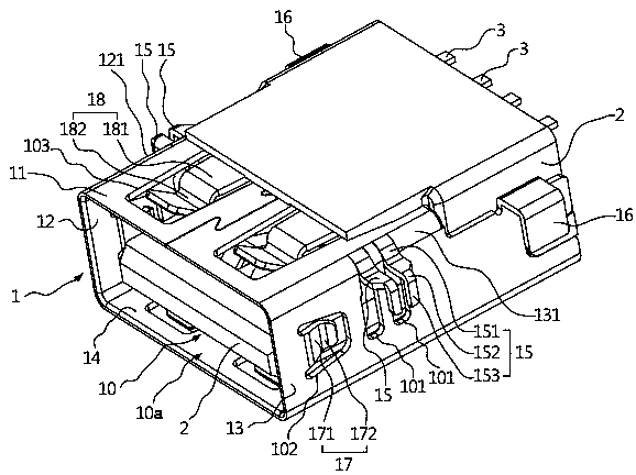
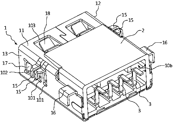
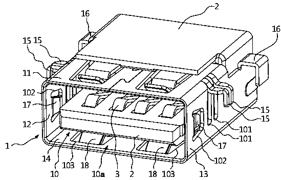
[0021] In the following description, in order to present the consistency of the description of the invention, in different embodiments, if there are components with the same or similar functions and structures, the same component symbols and names will be used. In addition, in order to clearly present the characteristics of this creation, some conventional components are omitted in the accompanying drawings. The directional terms mentioned in the embodiments, such as "upper", "lower", "left", "right", "front", "rear", etc., are only referring to the directions of the attached drawings, therefore, the used Directional terms are used to illustrate, not to limit this work.

[0022] Figure 1A , Figure 1B and Figure 1C It is a schematic diagram of the structure of the electrical connector of the preferred embodiment of the invention at different angles of view, figure 2 It is an exploded view of the structure of the electrical connector of the preferred embodiment of the in...


PUM

PropertyMeasurementUnit
Widthaaaaaaaaaa

Abstract

Provided is an electric connector. The electric connector comprises a metal shell body, an insulating body and a plurality of terminals. The metal shell body is provided with a top wall, two side walls, a bottom wall, a plurality of tearing type fixing pins and a plurality of extending type fixing pins, wherein a containing space, a first opening and a second opening are formed by the top wall, the two side walls and the bottom wall together, broken grooves are formed in the side walls by the tearing type fixing pins, each extending type fixing pin outwards extends relative to each side wall from one side edge, at the position of the second opening, of each side wall, and the width of each tearing type fixing pin is smaller than that of each extending type fixing pin. Due to the facts that traditional discharging type fixing pins which are arranged at the positions, close to a first opening in the front end of an electric connector, in a metal shell body are replaced by the tearing type fixing pins, and the broken grooves formed by the tearing type fixing pins in the side walls of the metal shell body are quite small in width, the safety requirement is met, the broken grooves do not need taping, and cost can be reduced.

Description

technical field [0001] The invention relates to an electrical connector, in particular to an electrical connector with tear-off fixing feet. Background technique [0002] Figure 5 It is a structural schematic diagram of a traditional electrical connector. See Figure 5 , the traditional electrical connector includes a metal shell 1', an insulating body 2' and a plurality of terminals 3'. The metal shell 1' has an accommodating space 10', a plurality of blanking-type fixing feet 15' and a plurality of extending-type fixing feet 16'. The insulating body 2' is disposed in the accommodating space 10' of the metal shell 1'. Each of the terminals 3' is disposed on the insulating body 2' and one end protrudes from the rear end of the electrical connector out of the accommodating space 10'. The blanking-type fixing feet 15' and the extending-type fixing feet 16' can be plugged into insertion holes provided on a circuit board (not shown) and the electrical connector is fixed on t...

Claims


Application Information

Patent Timeline
IPC IPC(8): H01R13/516H01R13/73H01R12/51
Inventor 陈庆典段术林万伟许夫义
Owner 连展科技电子(昆山)有限公司
Why Eureka
Try Eureka