Channel state information feedback method and device

A technology of channel state information and feedback mode, applied in the field of communication, can solve the problem of high CSI signaling overhead, etc.

Inactive Publication Date: 2013-10-23
ZTE CORP
View PDF5 Cites 15 Cited by
  • Summary
  • Abstract
  • Description
  • Claims
  • Application Information

AI Technical Summary

Problems solved by technology

[0010] Aiming at the problem that the CSI feedback method in the related art causes the base station to obtain relatively large CSI signaling overhead in the cooperative mode, the present invention provides a channel state information feedback method and device to at least solve this problem

Method used


Image

  • Channel state information feedback method and device
  • Channel state information feedback method and device
  • Channel state information feedback method and device

Examples


Embodiment 1

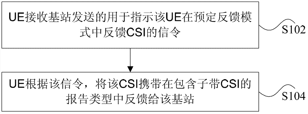
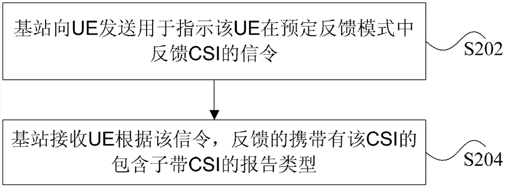
[0096] This preferred embodiment provides a CSI feedback method. In this embodiment, the aggregated CQI and / or PCI required for CoMP JT is periodically fed back, so as to provide timely cooperation information for the base station side and reduce aperiodic feedback. incoming signaling overhead.

[0097] The feedback method in this embodiment is as follows: in the periodic feedback mode 2-1 of the LTE R10 version, the high-level signaling that the base station side can pass indicates that the UE feeds back the aggregated CQI in the reporting type (reporting type) that includes subband CSI, And / or PCI, or the CQI of other CoMP cooperation methods indicated by the higher layer.

[0098]Preferably, in the physical uplink control channel reporting type 1 (PUCCH reporting type 1) of the 2 transmit antenna and 4 transmit antenna systems corresponding to the periodic feedback mode 2-1 or the PUCCH reporting type 1a of the 8 transmit antenna system, through various methods Feedback ag...

Embodiment 2

[0112] This preferred embodiment provides a CSI feedback method, and this embodiment is based on the CoMP JT system, such as Figure 5 As shown, three TPs constitute a cooperation set of UE, and in the cooperation set, there may be two TPs or three TPs for cooperation. The channels from TP1, TP2, and TP3 to the UE are H1, H2, and H3, respectively. Taking TP1 as the reference node, the phase difference between H2, H3 and H1 is θ 12 , θ 13 . Among them, θ 12 and θ 13 can be optimally chosen in a number of ways, for example,

[0113] Maximize signal combined received power:

[0114] θ ^ 12 , θ ^ 13 = max θ 12 , θ 13 ...

Embodiment 3

[0121] This embodiment provides a CSI feedback method, Figure 6 is a flow chart of feeding back aggregated CQI in the subband reporting type of feedback mode 2-1 according to an embodiment of the present invention, as shown in Figure 6 As shown, the method includes the following steps S602 to S610. Attached below Figure 6 The flow of this embodiment will be described in detail.

[0122] The CoMP JT system of this embodiment is such as Figure 5 As shown, TP1, TP2 and TP3 jointly send signals to the UE. Among them, TP1 is the main node or reference node, and TP2 and TP3 are cooperative nodes. Assume that periodic feedback is configured as Mode 2-1, that is, subband CQI selected by the UE, and wideband PMI. The 3 TPs are all 4 transmit antenna systems.

[0123] Step S602: The UE feeds back independent CSI (per-csi-rs resource CSI) reports of each TP on the PUCCH, and assumes interference outside the cooperating set.

[0124] Step S604: the base station side determines ...


PUM


Abstract

The invention discloses a channel state information (CSI) feedback method and device. The method includes: a set of UE receiving a signaling which is sent by a base station for instructing the UE to feed back the CSI in a preset feedback mode, wherein the CSI includes at least one of the following parts: a phase correct indicator (PCI) and a cooperation channel quality indicator (CQI) under a CoMP cooperation method which is instructed by a base station side through high-level signaling, wherein the cooperation CQI under the CoMP cooperation method which is instructed through the high-level signaling includes a CQI and/or an aggregated CQI which are/is determined on the basis of a predetermined interference value; and according to the signaling, the UE feeds back the CSI carried by a report type which includes the CSI of a sub-band, to the base station. Through the channel state information feedback method and device, reception performance of cooperation UEs is improved.

Description

technical field [0001] The present invention relates to the communication field, and in particular, relates to a channel state information (Channel State Information, CSI for short) feedback method and device. Background technique [0002] In order to improve the data throughput of edge users who suffer from large inter-cell interference in the cellular network, the Cooperate Multiple Point (Cooperate Multiple Point, CoMP for short) technology is proposed in the study of the Long Term Evolution (LTE for short) system. )technology. The CoMP technology includes joint transmission (Joint Transmission, referred to as JT). JT means that multiple sending nodes (TP) send data for user equipment (User Equipment, referred to as UE) on the same time-frequency resource through airspace cooperation to improve The signal power reduces interference at the same time, improves the receiving Signal Information Noise Ratio (SINR) of the UE, and improves the performance of the cell edge user....

Claims


Application Information

Patent Timeline
Patent Type & Authority Applications(China)
IPC IPC(8): H04B7/06
Inventor 郑勇孙云锋贺海港任敏张晨晨
Owner ZTE CORP
Why Eureka
Try Eureka