
A method and device for dividing cooperation areas in a wireless network

A wireless network and regional technology, applied in network planning, wireless communication, electrical components, etc., can solve the problem of scheduling complexity

Active Publication Date: 2016-08-17
IBM CORP
View PDF2 Cites 0 Cited by
  • Summary
  • Abstract
  • Description
  • Claims
  • Application Information

AI Technical Summary

Problems solved by technology

This method alleviates the edge effect of the collaboration area to a certain extent, but essentially still requires the interaction between different collaboration areas, there is still coupling between the collaboration areas, and the complexity of scheduling still exists

Method used


Image

  • A method and device for dividing cooperation areas in a wireless network
  • A method and device for dividing cooperation areas in a wireless network
  • A method and device for dividing cooperation areas in a wireless network

Examples


no. 1 example

[0036] Figure 4 It shows a schematic diagram of the division of the initial cooperation area according to the first embodiment of the present invention. Seven initial cooperation areas of the entire wireless network are determined according to the scope of the cooperation area and the positions of the base stations of each cell in the wireless network, and the seven initial cooperation areas are respectively Different line types are used for identification. Taking the initial cooperation area in the center as an example, the initial cooperation area is composed of cells 1-19, and cells 1-7 are not adjacent to other initial cooperation areas, so cells 1-7 form the In the internal area of ​​the initial cooperative area, the cells 8-19 are respectively adjacent to other cooperative areas, so the cells 8-19 constitute the external area of ​​the initial collaborative area.

[0037] Figure 5 A schematic diagram showing the division of the outer area according to the first embodim...

no. 2 example

[0041] Image 6 It shows a schematic diagram of the division of initial cooperation areas according to the second embodiment of the present invention. Seven initial cooperation areas are determined according to the scope of the cooperation area and the base stations of each cell in the wireless network, and the seven initial cooperation areas are respectively separated by different lines. In the wireless network of this embodiment, three cells share one base station. Taking the initial cooperation area in the center as an example, the initial cooperation area is composed of cells 1-21, and cells 1-21 are formed by seven base stations. Management control, where cells 1, 2, 3, 8, 13, 21 are not adjacent to other initial cooperation areas, so cells 1, 2, 3, 8, 13, 21 constitute the internal area of ​​the initial cooperation area, cells 4, Cells 5, 6, 7, 9, 10, 11, 12, 14, 15, 16, 17, 18, 19, and 20 are respectively adjacent to other cooperation areas, so cells 4, 5, 6, 7, 9, 10, ...


PUM


Abstract

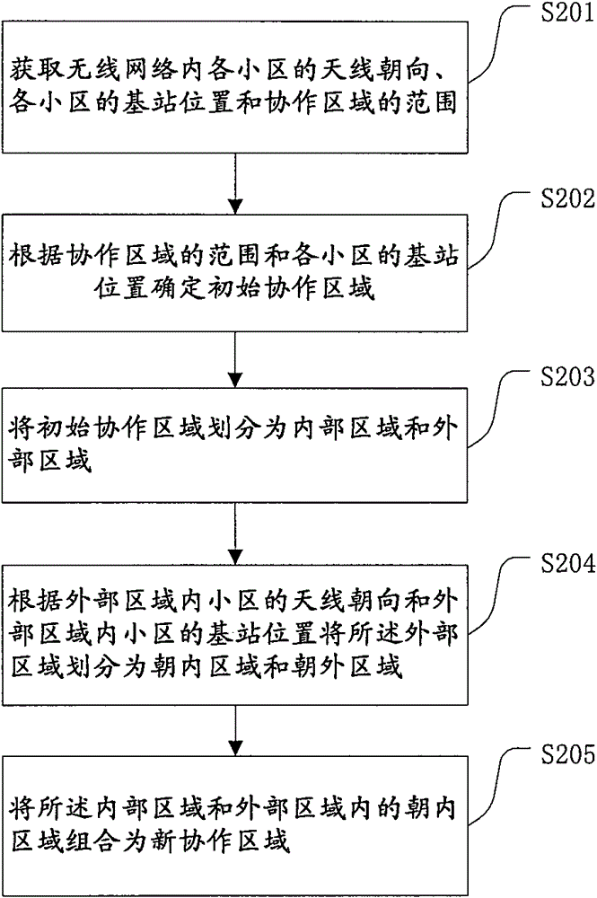
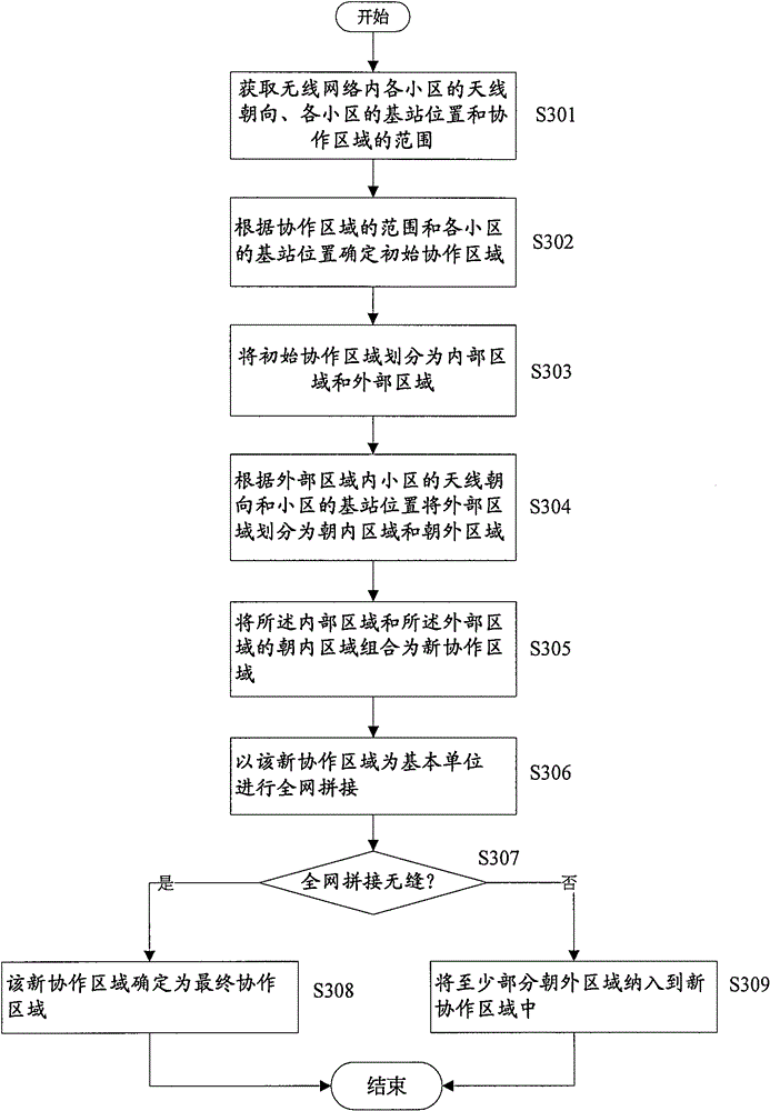
The present invention relates to a wireless network, and more specifically, to a method and apparatus for partitioning a coordination area in a wireless network, the method comprising: obtaining antenna directions of respective cells, base station locations of respective cells, and scope of a coordination area within the wireless network; determining an initial coordination area based on the scope of the coordination area and the base station locations in respective cells; partitioning the initial coordination area into an inner area and an outer area; partitioning the outer area into an inward area and an outward area based on the antenna directions of cells within the outer area and the base station locations of cells within the outer area; and combining the inner area and the inward area within the outer area into a new coordination area. The method is simple and easy. It may solve a problem of coordination area edge caused by partitioning a coordination area and meanwhile avoid the association between coordination areas, thereby reducing the complexity of scheduling.

Description

technical field [0001] The present invention relates to a wireless network, in particular to a method and a device for dividing cooperation areas in the wireless network. Background technique [0002] As people's demand for wireless network data services continues to increase, how to improve system throughput and spectrum efficiency as much as possible has become the focus of next-generation wireless networks. The cooperation between base stations is an important technology to fully obtain the potential capacity of the system. Through the interaction between cells, the local information of each cell can be fully utilized, and network resources can be coordinated and scheduled to obtain better global performance. The first step of cooperation is to determine the area of ​​cooperation and determine the base station and cell of cooperation. [0003] Generally speaking, there are three methods to determine the coordinated cell: the network decision method, the user decision me...

Claims


Application Information

Patent Timeline
Patent Type & Authority Patents(China)
IPC IPC(8): H04W16/18
CPCH04W16/30H04W16/12H04W16/02
Inventor 薛超林咏华阎蓉李明强祝超占海
Owner IBM CORP
Learn More