Supercharge Your Innovation With Domain-Expert AI Agents!

Heat radiation device and assembling method thereof

A heat sink and heat sink technology, applied in the direction of indirect heat exchangers, heat exchange equipment, heat exchanger fixation, etc., can solve the problems of the heat dissipation efficiency of the heat sink and the high manufacturing cost of the heat sink, and achieve low cost and high heat dissipation efficiency , The effect of low thermal resistance

Active Publication Date: 2013-10-23
CHAMP TECH OPTICAL FOSHAN
View PDF4 Cites 1 Cited by
  • Summary
  • Abstract
  • Description
  • Claims
  • Application Information

AI Technical Summary

Problems solved by technology

In this case, due to the thermal resistance of the solder paste, the heat dissipation efficiency of the heat sink is affected; at the same time, due to the need for electroplating and soldering, the manufacturing cost of the heat sink is relatively high

Method used


Image

  • Heat radiation device and assembling method thereof
  • Heat radiation device and assembling method thereof
  • Heat radiation device and assembling method thereof

Examples


Embodiment Construction

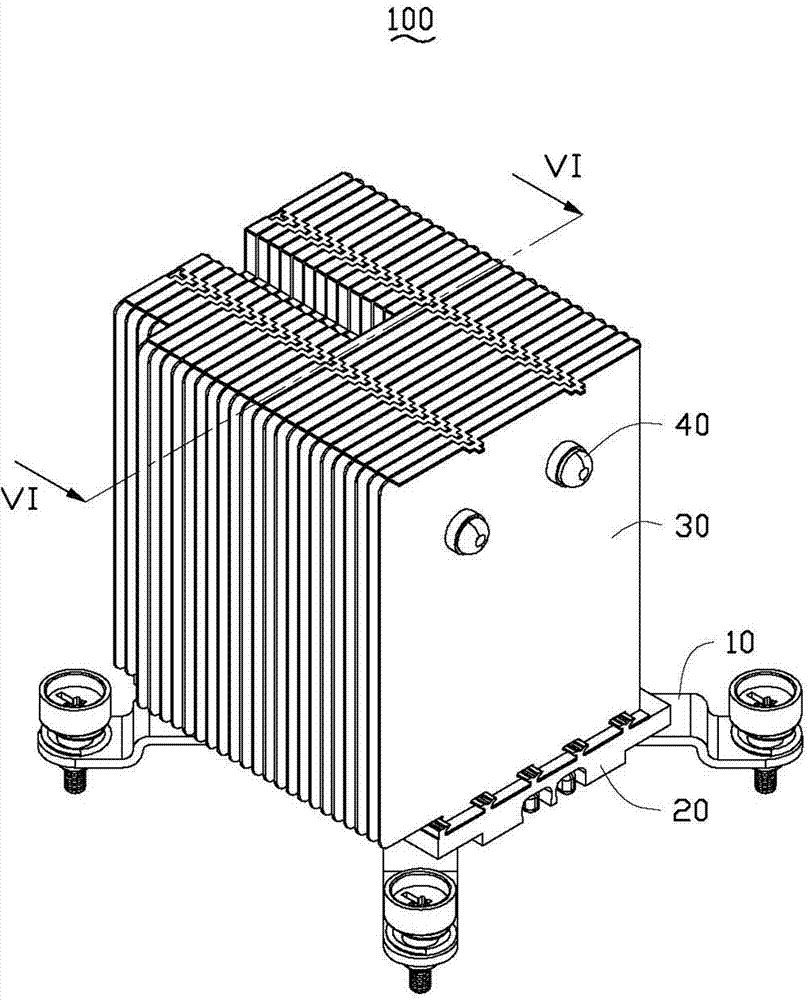
[0018] figure 1 Shown is the three-dimensional structure of the heat sink 100 provided by the embodiment of the present invention.

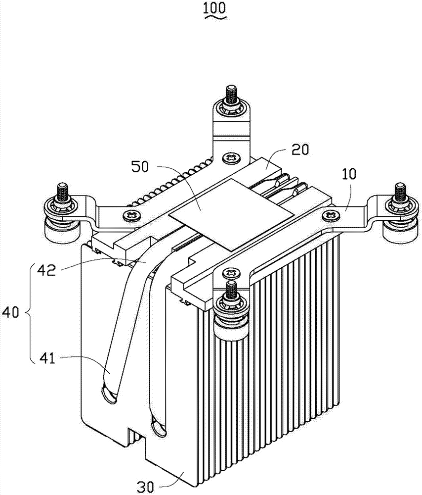
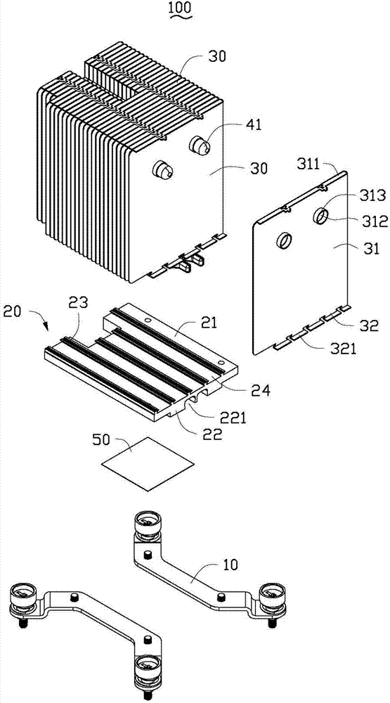
[0019] Please also see figure 2 and image 3 , the heat dissipation device 100 includes a bracket 10 , a base 20 , a heat sink set 30 and two U-shaped heat pipes 40 connecting the base 20 and the heat sink set 30 .

[0020] The bracket 10 cooperates with the base 20 for fixing the heat sink 100 on an external device to dissipate heat from the heat-generating electronic components.

[0021] See also Figure 4 , the base 20 is roughly rectangular and made of metal with good thermal conductivity, such as copper, aluminum and other materials. The base 20 has a top surface 21 and a bottom surface 22 corresponding thereto. A plurality of engaging parts 23 extending along the length direction of the base 20 are disposed on the top surface 21 of the base 20 . Each engaging member 23 includes an engaging end 231 and a supporting end 232 connecting ...


PUM


Abstract

A heat dissipation device includes a base and a plurality of fins. Two latch parts project from a top surface of the base, the two latch parts cooperatively define a recess therebetween. Each fin defines a tenon at a bottom portion. The tenon has a configuration in complement with that of the recess. The latch parts located between two neighboring fins is punched to make the fins fix on the base.

Description

technical field [0001] The invention relates to a heat dissipation device, in particular to a heat dissipation device for heat dissipation of electronic components and an assembly method thereof. Background technique [0002] With the continuous development of electronic industry technology, the operation speed of electronic components is accelerated, and the heat generated increases, which makes the temperature of the system and electronic components themselves rise. If the heat is not removed in time, it will lead to a decline in its working performance. In order to ensure the normal operation of the electronic components, a heat sink is usually installed on the surface to assist in heat dissipation. [0003] A traditional heat dissipation device includes a plurality of extruded aluminum heat sinks, a base plate located under the heat sinks, and a heat pipe interposed between the heat sinks and the base plate. These fins are nickel plated and soldered to the heat pipes. ...

Claims


Application Information

Patent Timeline
Patent Type & Authority Applications(China)
IPC IPC(8): H05K7/20
CPCH01L23/467H01L23/4006H05K7/20H01L23/427H01L21/4878H01L2924/0002Y10T29/4935F28F2275/14F28F1/32F28D15/0275H01L2924/00
Inventor 陈乔龙杨子富符猛陈俊吉
Owner CHAMP TECH OPTICAL FOSHAN
Features
  • R&D
  • Intellectual Property
  • Life Sciences
  • Materials
  • Tech Scout
  • Unparalleled Data Quality
  • Higher Quality Content
  • 60% Fewer Hallucinations
Learn More