Computed tomography (CT) device

A technology of fixing device and rack, applied in medical science, diagnosis, computer tomography scanner, etc., can solve the problems of complicated structure, labor-intensive, labor-saving not optimized, etc., to save open space and facilitate maintenance. Effect

Inactive Publication Date: 2013-10-30
KK TOSHIBA +1
View PDF2 Cites 11 Cited by
  • Summary
  • Abstract
  • Description
  • Claims
  • Application Information

AI Technical Summary

Problems solved by technology

[0005] However, there is such a problem in the opening structure of the front cover of the prior art: first, because the weight of the front cover of the CT frame is very large, it needs to support both sides, so two people are required to operate at the same time when opening, and it takes a lot of money to open it. manpower
Although the danger of the lifted cover hitting the head can be avoided through this structure, it still consumes manpower and space on the front side (closer side) of the rack body due to the large volume and weight of the cover.
[0007] Next, in Patent Document 2, although the front cover that can be opened by the hinge is provided with a mechanism that utilizes the power assist function of the spring bar to improve the operability, the structure is complicated because the mechanism needs to be provided with a telescoping mechanism and the like. It is not optimized in terms of labor saving

Method used


Image

  • Computed tomography (CT) device
  • Computed tomography (CT) device
  • Computed tomography (CT) device

Examples


no. 1 Embodiment approach

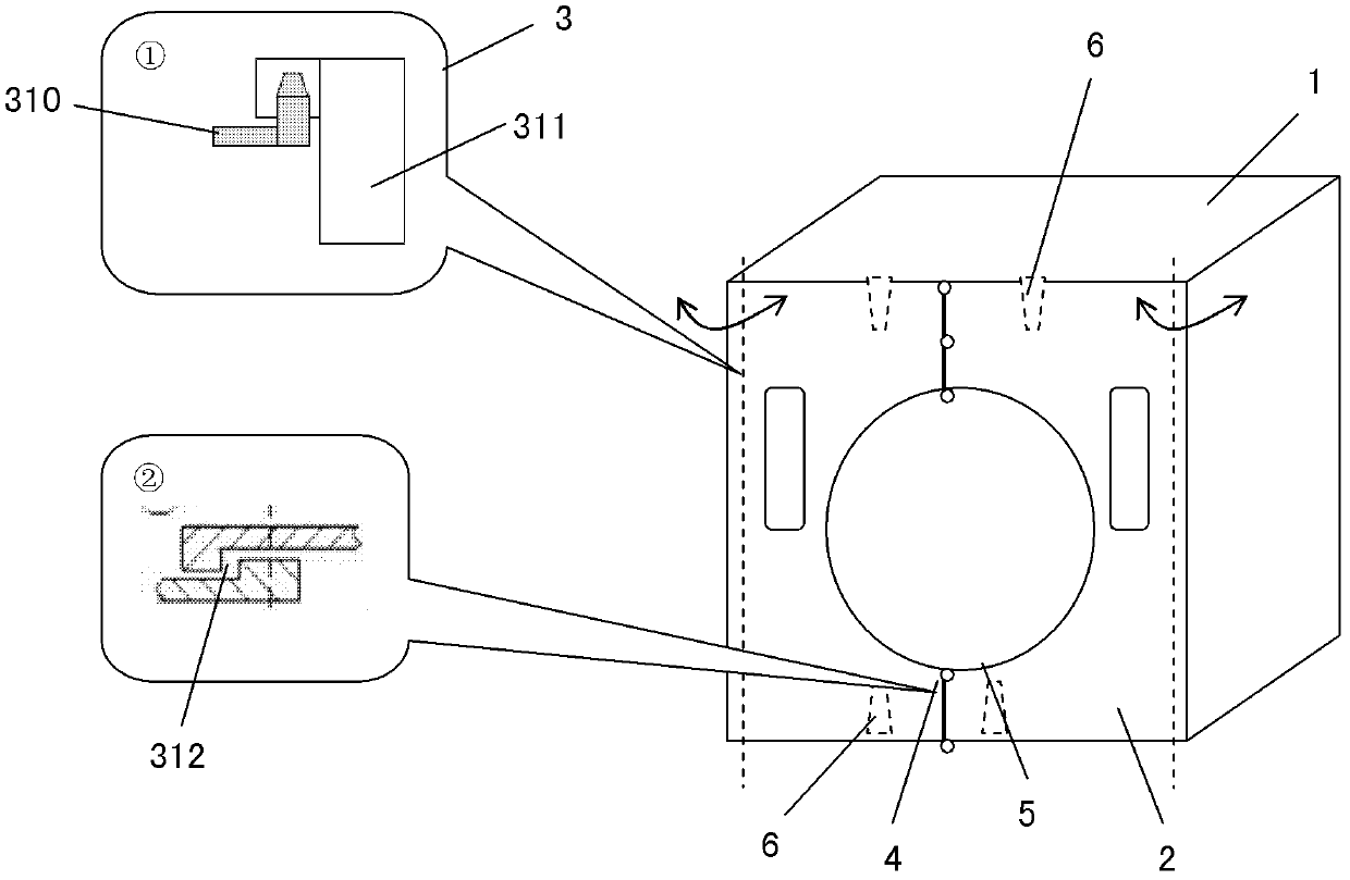
[0030] figure 1 It is a perspective view of the front cover of the first embodiment of the present invention. In this embodiment, as the figure 1 As shown, the front cover 2 is divided into left and right parts to form a left and right cover body, so that the front cover can be opened in a left and right way. If there is no special description below, the so-called "front side" refers to the side of the frame body 1 facing the operator, and the so-called "rear side" refers to the side opposite to the above-mentioned "front side" of the frame body 1, and the so-called " Left side" or "right side" refers to the left or right side of the operator facing the rack main body 1 for operation, and the so-called "upper side" and "lower side" refer to the top of the rack main body 1 erected on the ground. and below (above and below the drawing).

[0031] In the front cover opening structure of this embodiment, a hinge assembly 3 (such as figure 1 The partial enlargement is shown i...

no. 2 Embodiment approach

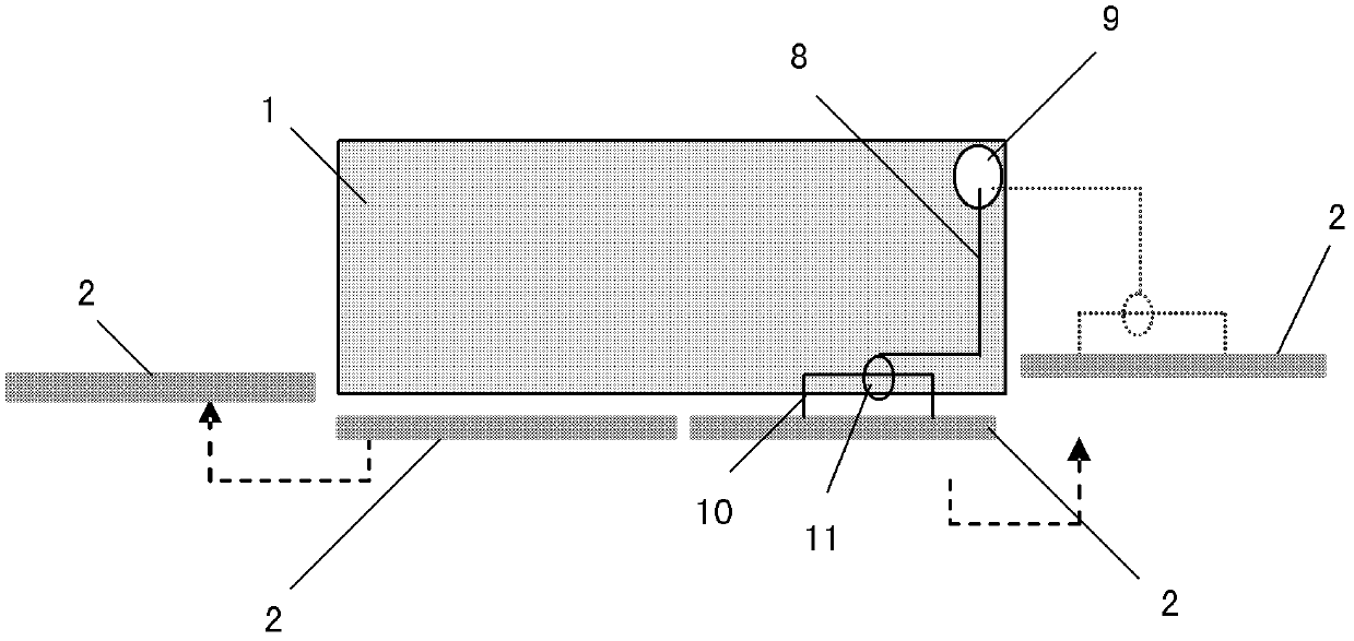
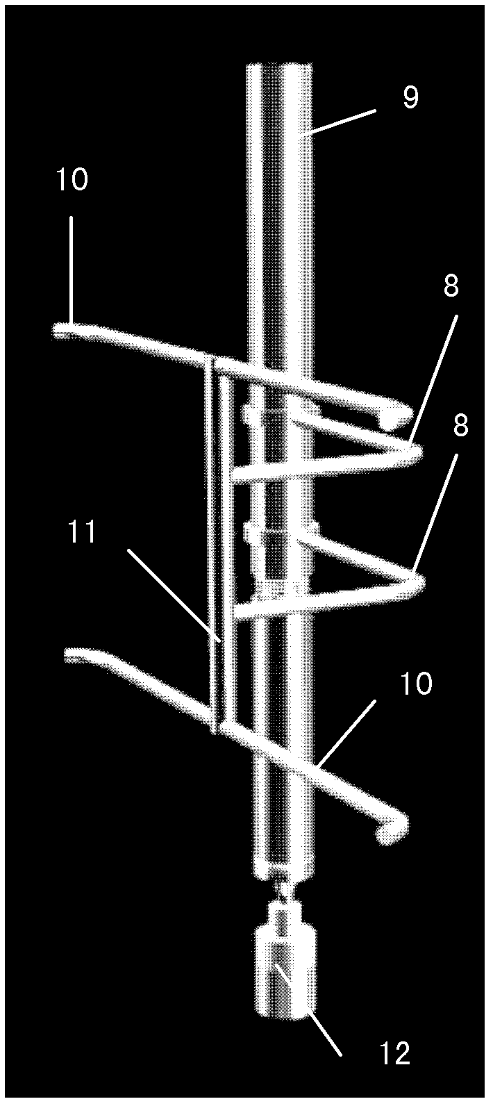
[0037] figure 2 It is a schematic top view of the opening structure of the front cover of the second embodiment of the present invention; image 3 It is a perspective view of a front cover rotation unit according to a second embodiment of the invention. In this embodiment, the same reference numerals are attached to the same structures as those in the above-mentioned embodiment, and redundant descriptions are omitted.

[0038] In this embodiment, the structure of the front cover rotation unit is as follows: two support rods 10 are respectively fixed on the left and right covers, the two ends of the rotating shaft 11 are rotatably connected to the support rods 10, and the "L" shaped One end of the support rod 8 is fixedly connected to the middle part of the rotating shaft 11 , and the other end is rotatably connected to the fixed shaft 9 , and two of them are arranged in parallel along the up-down direction. However, the number is not limited to two, and may be one or more t...

no. 3 Embodiment approach

[0043] Figure 4 (a) is a rear view of the front cover of the third embodiment of the present invention, Figure 4 (b) is a plan view of the front cover of the third embodiment of the present invention; Figure 5 It is a schematic diagram of the opening operation of the front cover of the third embodiment of the present invention. In this embodiment, the same reference numerals are assigned to the same structures as those in the above-mentioned embodiment, and overlapping descriptions are omitted.

[0044] In this embodiment, the left and right covers are rotatably fixed on the fixed shafts 13 provided on the left and right sides through the shafts 14 ′ and the fixing device 12 respectively, so that the left and right covers and the fixing device 12 can move relative to the fixed shaft 13 rotation, and the left and right covers can rotate relative to the fixing device 12 through the shaft 14'. One end of the shaft 14 is rotatably fixed on the fixing device 15 installed on t...


PUM


Abstract

According to one embodiment, a CT apparatus includes a gantry main body and a front cover covering a front surface side of the gantry main body, and the front cover includes two cover segments which are held to be configured to open to left and right sides, the cover segments being configured to open or close manually or by being motor-driven by a front cover opening structure.

Description

technical field [0001] The present invention relates to a front cover opening structure of a CT rack (CT Gantry) in a CT device, in particular to a structure capable of safely and conveniently opening the front cover of a CT rack, and using the front cover with the structure The CT device and its front cover opening method. Background technique [0002] With the continuous development and expansion of hospitals and the continuous updating of large-scale equipment, after years of development, the structure of CT devices has been greatly improved, the number of detector layers has continued to increase, and the scanning speed has continued to accelerate. There are also many types. However, its hardware composition is basically the same, and there are three main parts: a scanning frame with an X-ray generating part and a detector, a console with a computer, and a movable examination bed. Press the button, and the examination table will slowly move forward or backward. A disp...

Claims


Application Information

Patent Timeline
Patent Type & Authority Applications(China)
IPC IPC(8): A61B6/03
CPCA61B6/44A61B6/035
Inventor 彭莉孙俊杰于凤波谢成豪
Owner KK TOSHIBA
Why Eureka
Try Eureka