Manual engagement and disengagement mechanism of electric actuator

A technology of electric actuator and clutch mechanism, applied in the direction of engine components, mechanical equipment, valve operation/release devices, etc., can solve the problems of difficult movement, difficult to manually operate the actuator, and inconvenience.

Pending Publication Date: 2020-07-03
温州合力自动化仪表有限公司
View PDF0 Cites 3 Cited by
  • Summary
  • Abstract
  • Description
  • Claims
  • Application Information

AI Technical Summary

Problems solved by technology

A kind of manual clutch of the current electric actuator is that the handwheel is not connected to the worm, but directly drives the output by the handwheel. The problem is that it will be particularly difficult to perform manual switching in places with large torque output. In the case of a stuck valve, the worm gear Self-locking, the output force is always maintained, so that the clutch switch does not move
Anoth

Method used


Image

  • Manual engagement and disengagement mechanism of electric actuator
  • Manual engagement and disengagement mechanism of electric actuator
  • Manual engagement and disengagement mechanism of electric actuator

Examples


Embodiment Construction

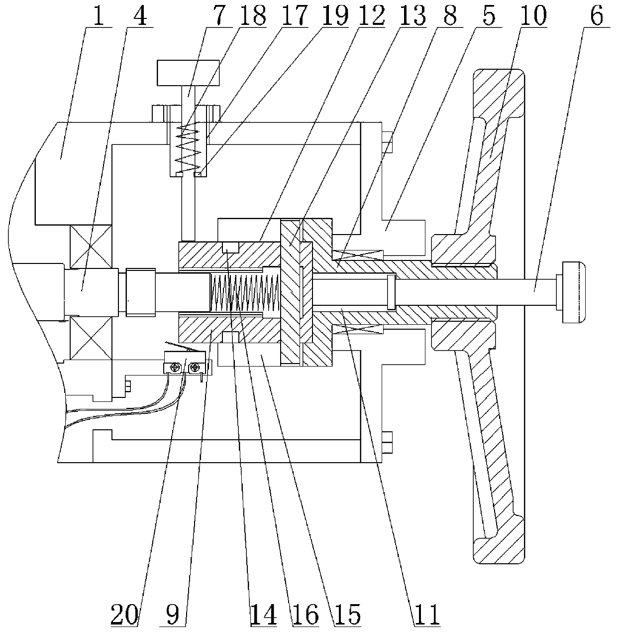
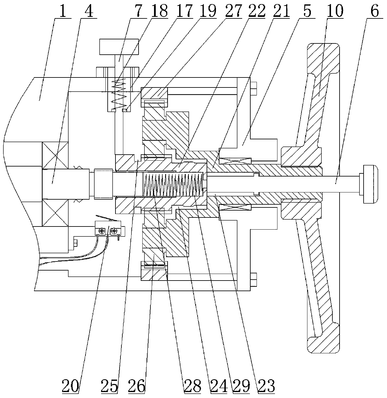
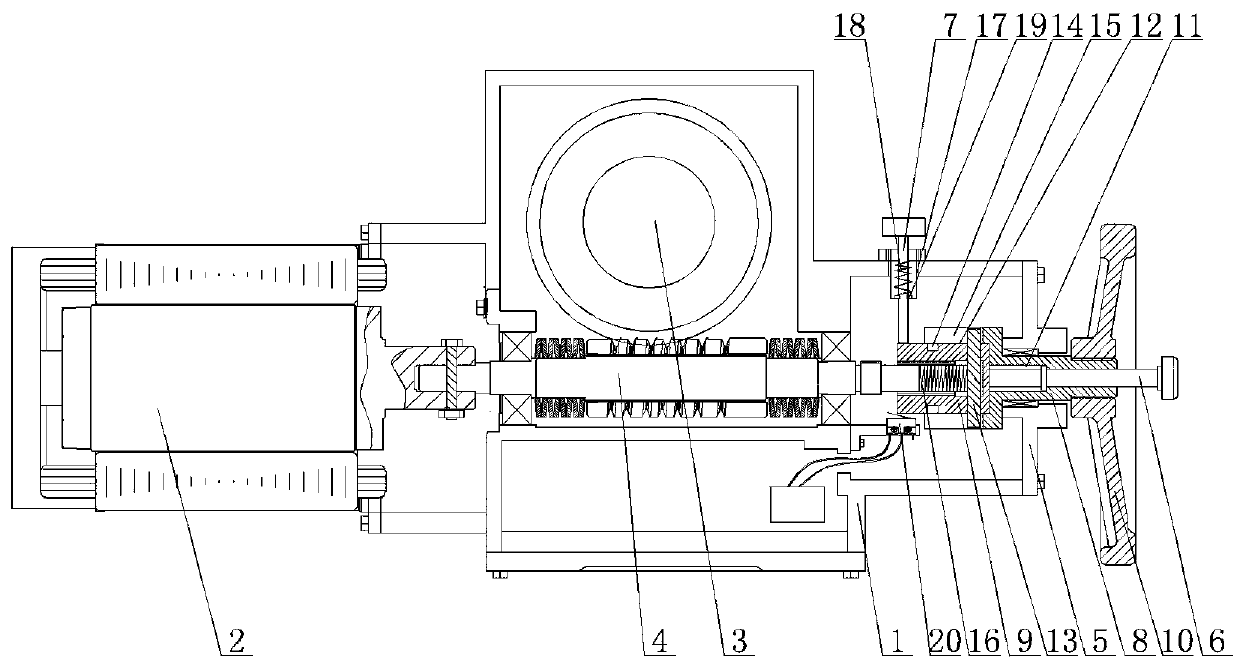
[0016] refer to figure 1 and image 3 As shown, the first embodiment of the manual clutch mechanism of an electric actuator provided by the present invention belongs to the direct-drive manual clutch mode, including a box body 1 and a motor 2 arranged in the box body 1, and mutually meshed The worm gear 3 and the worm 4, the other side of the box body 1 is detachably provided with a hand wheel 10 end cover 5 through bolts, one end of the worm 4 is connected to the rotating shaft of the motor 2, the motor 2 is connected to a power supply, and the end cover 5 of the hand wheel 10 is movable There is a push rod 6, and the inner side of the push rod 6 can drive the worm 4 to rotate through the linkage device. The pull pin 7 that can be inserted into the linkage device is movable on the box body 1. The pull pin 7 is equipped with a reset device. The linkage device includes a handwheel shaft 8 and The inner spline sleeve 9, the handwheel shaft 8 is rotated and installed on the end ...


PUM


Abstract

The invention discloses a manual engagement and disengagement mechanism of an electric actuator. The manual engagement and disengagement mechanism comprises a box body, a motor, a worm wheel and a worm, wherein the motor, the worm wheel and the worm are arranged in the box body, and the worm wheel and the worm mesh with each other; a hand wheel end cover is detachably arranged on one side of the box body through bolts; one end of the worm is connected with a rotating shaft of the motor; and the motor is connected with a power supply. The manual engagement and disengagement mechanism is characterized in that an ejector rod movably penetrates through the hand wheel end cover, the inner side of the ejector rod can drive the worm to rotate through a linkage device, a pull pin capable of beinginserted into the linkage device movably penetrates through the box body, and the pull pin is provided with a resetting device. The linkage device of the manual engagement and disengagement mechanismof the electric actuator comprises a direct driving mode and a speed increasing mode, so that the stock and die input of part production are greatly reduced, and the requirements of different customers on multiple turns of the actuator and easy shaking of a hand wheel can be met; two manual engagement and disengagement modes are set in the box body and share a microswitch, an inner spline sleeve or a central wheel is pushed by pressing the ejector rod by hand, the inner spline sleeve or the central wheel can also abut against the microswitch to cut off the power supply of the motor firstly soas to stop the motor, and thus a valve can be opened or closed safely even under the condition of misoperation of the hand wheel.

Description

technical field [0001] The invention relates to a manual clutch mechanism of an electric actuator. Background technique [0002] Electric actuators are mainly used in the automatic control of on-off valves, through which the valves can be automatically controlled locally or remotely, and are widely used in hydropower, petroleum, chemical and other fields. A kind of manual clutch of the current electric actuator is that the handwheel is not connected to the worm, but directly drives the output by the handwheel. The problem is that it will be particularly difficult to perform manual switching in places with large torque output. In the case of a stuck valve, the worm gear Self-locking, the output force is always maintained, so that the clutch switching does not move. Another manual clutch of the electric actuator is that the handwheel is connected to the worm, but it is necessary to shake the handwheel while pushing the handwheel, that is, the handwheel needs force in two dire...

Claims


Application Information

Patent Timeline
IPC IPC(8): F16K31/05F16K31/53
CPCF16K31/046F16K31/047F16K31/05F16K31/53
Inventor 郑纬郑阳戴承浩梁水清
Owner 温州合力自动化仪表有限公司
Why Eureka
Try Eureka