Punching device for bookbinding machine

A technology of punching device and binding machine, which is applied in the direction of metal processing, etc., can solve the problems of disassembly and installation trouble, disassembly and installation speed, etc., and achieve the effect of smooth chip removal, quick disassembly and quick installation

Inactive Publication Date: 2013-10-30
ZHEJIANG ZHIYUAN OFFICE EQUIP MFG
View PDF1 Cites 6 Cited by
  • Summary
  • Abstract
  • Description
  • Claims
  • Application Information

AI Technical Summary

Problems solved by technology

[0002] At present, for the binding of paper, documents, and albums, the riveting binding method is generally used, which includes steps such as punching, pipe cutting, and riveting. When punching holes, the punching device of the binding machine is needed. The earliest The punching device is just a simple hollow rod that punches holes in the bound documents under manual pressure. Later, people improved it. For example, the patent application number is CN201120216264.2, and the application date is June 2011 The Chinese invention patent on the 24th disclosed a hole drilling mechanism with an automatic paper dust collection device, which uses a motor to drive the cutter to rotate, the drilling speed is fast, and the paper dust can be quickly discharged. However, the existing In the punching device, the installation between the tool and the rotating spindle is fixedly connected, which is very troublesome to disassemble and install, and the speed of disassembly and installation is slow

Method used


Image

  • Punching device for bookbinding machine
  • Punching device for bookbinding machine
  • Punching device for bookbinding machine

Examples


Embodiment 1

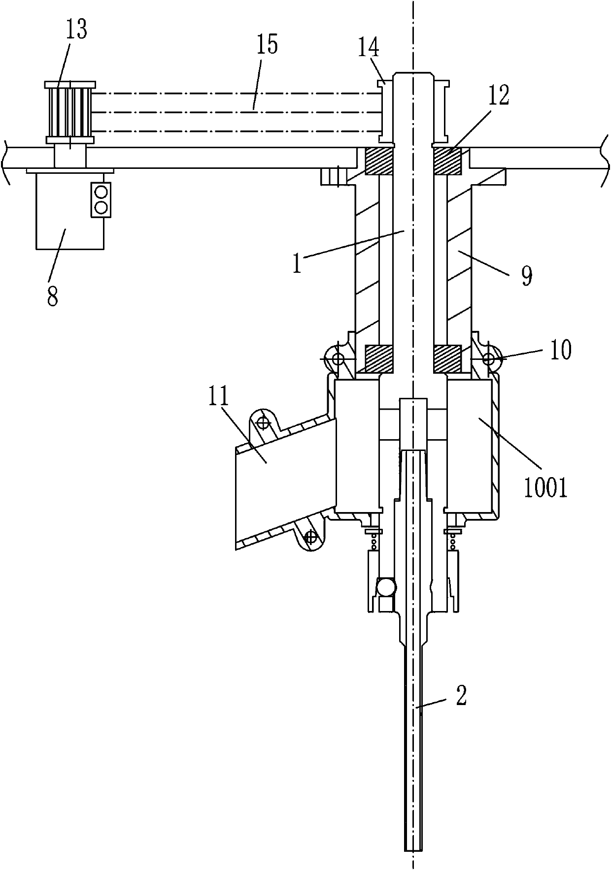
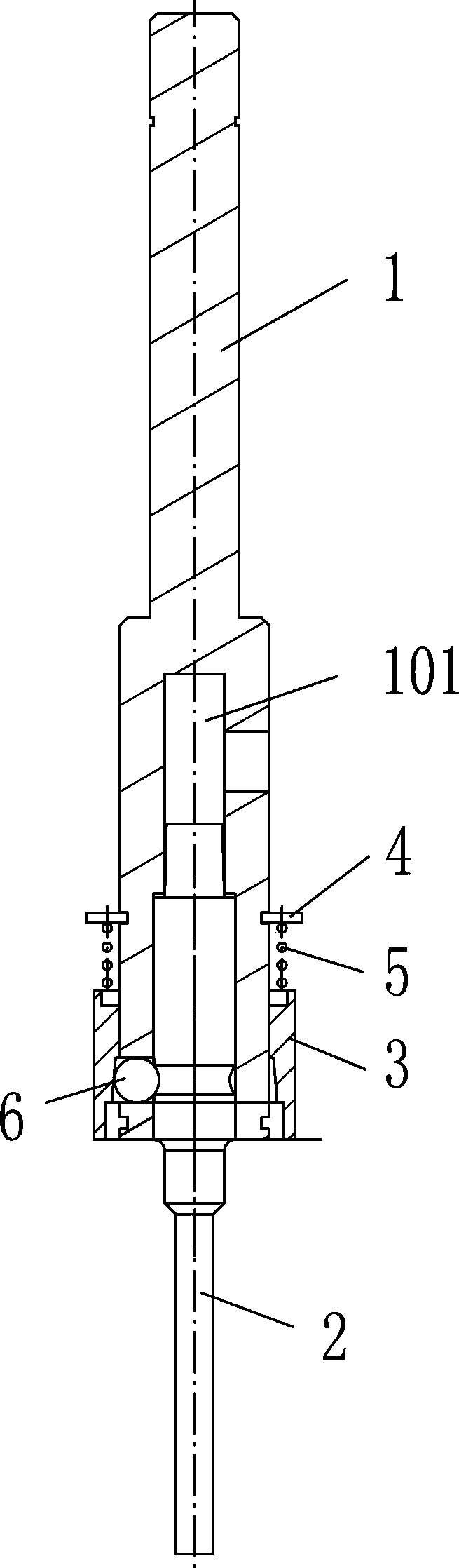
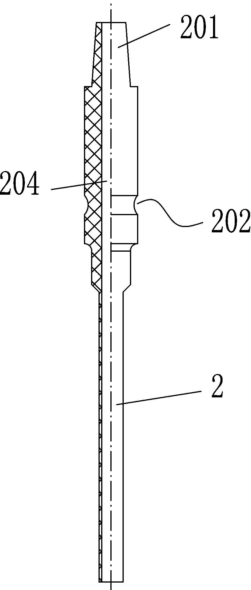
[0024] Embodiment 1, see attached figure 1 , 2 , 3, 4, 5, a punching device for a bookbinding machine, including a main shaft 1 with a connection cavity 101, a motor 8 for driving the main shaft to rotate, a cutter 2 with an inner hole 204 and an axle seat 9 for installing the main shaft , a bearing 12 is provided in the shaft seat 9, the inner ring of the bearing is connected to the main shaft, and the outer ring is fixedly connected to the shaft seat. There are two bearings 12, which are arranged at the upper and lower ends of the shaft seat. A driving wheel 13 is provided, and a driven wheel 14 is arranged on the main shaft, and the driving wheel 13 and the driven wheel 14 are connected by a transmission belt 15, of course, the driving wheel and the driven wheel can adopt mutually meshing gears. The upper end of the tool 2 is provided with a connecting block 201 fixedly connected to the connecting cavity 101, the inner hole 204 communicates with the connecting cavity 101, ...

Embodiment 2

[0027] Embodiment 2, see attached Image 6 , in this embodiment, the anti-disengagement connection mechanism includes a ball plunger 7 installed on the main shaft, and the tool is provided with a clamping hole 203 that matches the spherical plunger. Similarly, the clamping hole It is an annular groove extending along the entire outer peripheral surface of the tool. The number of clamping holes and ball plungers is determined according to the actual situation, generally 3, and the ball plungers are installed in the through hole 103 of the main shaft. The rest are the same as in Embodiment 1. Compared with Embodiment 1, the structure of this embodiment is simpler.


PUM


Abstract

The invention discloses a punching device for a bookbinding machine. The punching device for the bookbinding machine comprises a main shaft which is provided with a connecting chamber, a motor which drives the main shaft to rotate, a cutting tool which is provided with an internal hole and a shaft seat which is used for installing the main shaft; the upper end of the cutting tool is provided with a connecting block which is fixedly connected with the connecting chamber; the internal hole is communicated with the connecting chamber; a scrap collecting sleeve is arranged on the main shaft; a scrap collecting chamber is arranged inside the scrap collecting sleeve; the connecting chamber is communicated with the scrap collecting chamber through a connecting hole which is formed in the main shaft; a scrap discharging pipe is arranged on the scrap collecting chamber; a looseness proof connecting structure which enables the main shaft and the cutting tool to be connected is arranged on the main shaft and the cutting tool. The punching device for the bookbinding machine has the advantages of rapidly discharging the paper scraps, preventing the cutting tool from being broken and enabling detachment and installation between the cutting tool and the main shaft to be rapidly achieved.

Description

technical field [0001] The invention relates to the technical field of office supplies, in particular to a punching device for a bookbinding machine. Background technique [0002] At present, for the binding of paper, documents, and albums, the riveting binding method is generally used, which includes steps such as punching, pipe cutting, and riveting. When punching holes, the punching device of the binding machine is needed. The earliest The punching device is just a simple hollow rod that punches holes in the bound documents under manual pressure. Later, people improved it. For example, the patent application number is CN201120216264.2, and the application date is June 2011 The Chinese invention patent on the 24th disclosed a hole drilling mechanism with an automatic paper dust collection device, which uses a motor to drive the cutter to rotate, the drilling speed is fast, and the paper dust can be quickly discharged. However, the existing In the punching device, the inst...

Claims


Application Information

Patent Timeline
Patent Type & Authority Applications(China)
IPC IPC(8): B26F1/16B26D7/18B26D7/26
Inventor 王超棣阮永华
Owner ZHEJIANG ZHIYUAN OFFICE EQUIP MFG
Why Eureka
Try Eureka