lighting equipment

A technology for light-emitting equipment and light-emitting elements, which is applied to lighting and heating equipment, light sources, semiconductor devices of light-emitting elements, etc. Effects of reduced uniformity, simplified structure, large light distribution angle

Active Publication Date: 2017-12-26
LEDVANCE GMBH
View PDF8 Cites 0 Cited by
  • Summary
  • Abstract
  • Description
  • Claims
  • Application Information

AI Technical Summary

Problems solved by technology

[0008] Moreover, the structure of the existing LED lamp tube 1 is relatively complicated, and bolts are usually used to fix the mounting part 4, the connecting layer 6, the radiator 3, etc.
[0009] Also, since each LED element needs to dissipate heat, a certain distance needs to be kept between each LED element, which affects the uniformity (uniformity) of the LED light tube.
[0010] Finally, the existing LED lamp tube 1 usually needs to be provided with a heat sink 3 made of metal material, thereby increasing the weight of the entire lamp tube
[0011] It needs to be understood that although the above descriptions are some problems existing in the existing LED lamp tubes, similar problems will also exist in light-emitting devices that use other light-emitting elements with similar light-emitting characteristics to LEDs as light sources

Method used


Image

  • lighting equipment
  • lighting equipment
  • lighting equipment

Examples


Embodiment Construction

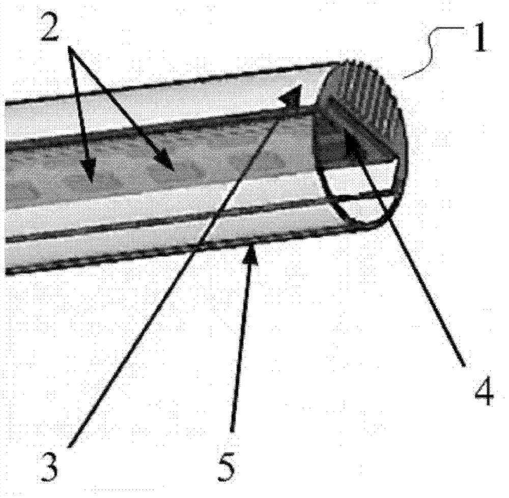
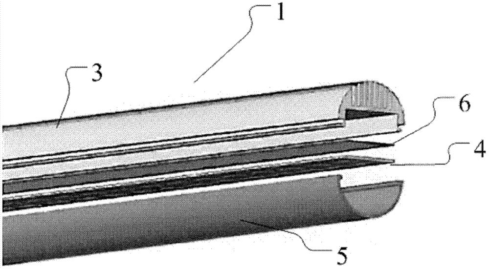
[0033] According to an embodiment of the present disclosure, there is provided a light emitting device, which includes: a light emitting element, which emits light with different intensities in different directions; a mounting part, on which the light emitting element is mounted; and a housing, which is used to accommodate the light emitting element. components and mounting parts. Wherein, at least a part of the housing is formed as a light-transmitting area, so that the light emitted from the light-emitting element can pass through the light-transmitting area and be emitted to the outside of the light-emitting device; the thickness of the light-transmitting area at each position is the same as the light emitted by the light-emitting element. The intensity in the direction pointing to the position is negatively correlated; and the thickness of the light-transmitting region at each position is gradually changed. Various embodiments and modifications of the present disclosure wi...


PUM


Abstract

The invention relates to light-emitting equipment which comprises a light-emitting element, a mounting part and a housing. Light emitted by the light-emitting element is different in intensity in different directions, the light-emitting element is mounted on the mounting part, and the housing is used for accommodating the light-emitting element and the mounting part. At least one part of the housing is formed into a light-transmitting area to enable the light emitted by the light-emitting element to be capable of penetrating the light-transmitting area to be emitted to the outside of the light-emitting equipment; moreover, the thickness of each position of the light-transmitting area is in negative correlation with the intensity of the light emitted by the light-emitting element in the direction of the position. By the arrangement, the intensity of the light emitted by the light-emitting element in all directions becomes more isotropic.

Description

technical field [0001] The present disclosure relates to a light emitting device, and more particularly, to a light emitting device having light emitting elements with different light emitting intensities in different directions. Background technique [0002] Conventional fluorescent lamps are often constructed in the form of tubes. Because the fluorescent lamp tube contains the heavy metal substance "mercury", the pollution to the environment is very serious. In recent years, as LEDs are increasingly used in various fields such as lighting, LED lamp tubes appear to replace traditional fluorescent lamp tubes. LED lamps use light-emitting diodes (LEDs) as light sources, which have higher luminous efficiency, more energy-saving, longer service life, and are more environmentally friendly, so they have become the most ideal products to replace fluorescent lamps. [0003] figure 1 It is a perspective view showing the main structure of a conventional LED lamp tube 1 . Wherein ...

Claims


Application Information

Patent Timeline
Patent Type & Authority Patents(China)
IPC IPC(8): F21K9/275F21V19/00F21V5/00F21Y115/10F21V29/50
CPCF21K9/27F21Y2103/10F21Y2107/90F21Y2115/10
Inventor 刘廷明陈鹏李皓郑盛梅
Owner LEDVANCE GMBH
Why Eureka
Try Eureka