
Digital optical processor projector and displaying method thereof

A technology of digital optics and display methods, applied in optics, instruments, electrical components, etc., can solve problems such as unable to automatically correct synchronization signals

Active Publication Date: 2013-10-30
ACER INC
View PDF4 Cites 1 Cited by
  • Summary
  • Abstract
  • Description
  • Claims
  • Application Information

AI Technical Summary

Problems solved by technology

Moreover, the traditional image content does not contain information indicating whether the display data is a left-eye image or a right-eye image, so it is impossible to judge whether the display data is a left-eye image or a right-eye image through the image content according to traditional display technologies, that is, it cannot be automatically corrected sync signal

Method used


Image

  • Digital optical processor projector and displaying method thereof
  • Digital optical processor projector and displaying method thereof
  • Digital optical processor projector and displaying method thereof

Examples


Embodiment Construction

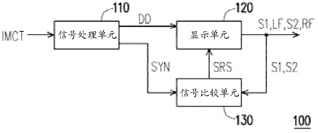
[0047] figure 1 It is a system diagram of a projector according to an embodiment of the present invention. Please refer to figure 1 , in this embodiment, the projector 100 is an example of a digital optical processor projector. The projector 100 includes a signal processing unit 110 , a display unit 120 and a signal comparison unit 130 . In an embodiment of the present invention, the display unit 120 and the signal comparison unit 130 can be integrated into a display chip or a display circuit, but the embodiment of the present invention is not limited thereto.

[0048] The signal processing unit 110 receives the image content IMCT, and generates display data DD and synchronization information SYN according to the image content IMCT after performing data processing on the image content IMCT. Wherein, the display data DD can be left-eye frame data or right-eye frame data, and the synchronization information SYN is used to indicate that the display data DD is left-eye frame da...


PUM


Abstract

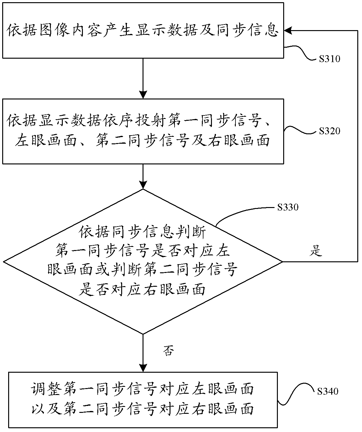
The invention provides a digital optical processor projector and a displaying method of the digital optical processor projector. The digital optical processor projector comprises a signal processing unit, a displaying unit and a signal comparing unit. The signal processing unit generates displaying data and synchronous information according to the content of images. The displaying unit sequentially projects a first synchronous signal, the image of the left eye, a second synchronous signal and the image of right eye according to the displaying data. The signal comparing unit judges whether the first synchronous signal corresponds to the image of the left eye or judges whether the second synchronous signal corresponds to the image of the right eye according to the synchronous information. When the first synchronous signal does not correspond to the image of the left eye or the second synchronous signal does not correspond to the image of the right eye, the signal comparing unit outputs a synchronous correction signal to the displaying unit to adjust the first synchronous signal and enable the first synchronous signal to correspond to the image of the first eye or adjust the second synchronous signal and enable the second synchronous signal to correspond to the image of the right eye.

Description

technical field [0001] The present invention relates to a projector and its display method, and in particular to a digital optical processor projector and its display method. Background technique [0002] With the evolution of projection display technology, projection systems and equipment have developed significantly in recent years. The principle of a projector is similar to that of a slide or a slide, all of which use a high-brightness light bulb as a light source to project the picture onto a white curtain or wall. In terms of technical principles, the more common projectors on the market are high-temperature polysilicon (Polysilicon) transmissive liquid crystal displays (commonly referred to as liquid crystal projectors) and digital optical processor (Digital Light Processing, DLP) projectors. Among them, the technical principle of the digital optical processor projector is to use the rotating color wheel (colorwheel) to divide the light of the light source into three ...

Claims


Application Information

Patent Timeline
IPC IPC(8): H04N13/04G03B21/00
Inventor 苏镇港陈信宇
Owner ACER INC
Learn More