Drive system for a ball mill and method for operating a ball mill

A drive system, ball mill technology, applied in the field of ball mill drive system and running ball mill

Active Publication Date: 2013-10-30
SIEMENS AG
View PDF4 Cites 2 Cited by
  • Summary
  • Abstract
  • Description
  • Claims
  • Application Information

AI Technical Summary

Problems solved by technology

The reason why the known systems for ring motors cannot be used in wound rotor motors is that they can only control the drive in the form of wound rotor motors, but cannot regulate them
As a result, it is not possible to move or shake the agglomerates in the mill with standard drives, that is to say with wound rotor motors, as used in known methods.

Method used


Image

  • Drive system for a ball mill and method for operating a ball mill
  • Drive system for a ball mill and method for operating a ball mill
  • Drive system for a ball mill and method for operating a ball mill

Examples


Embodiment Construction

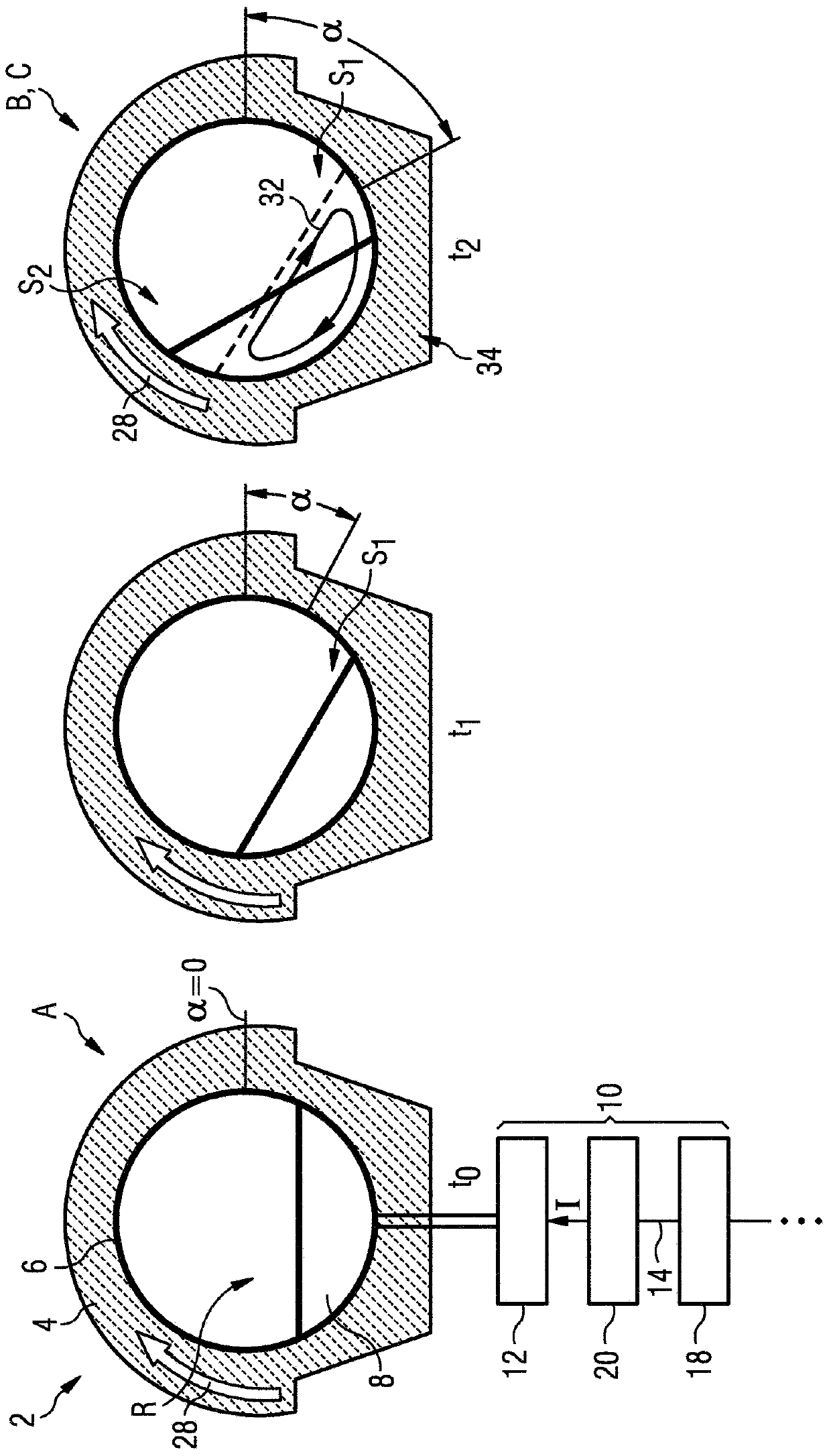
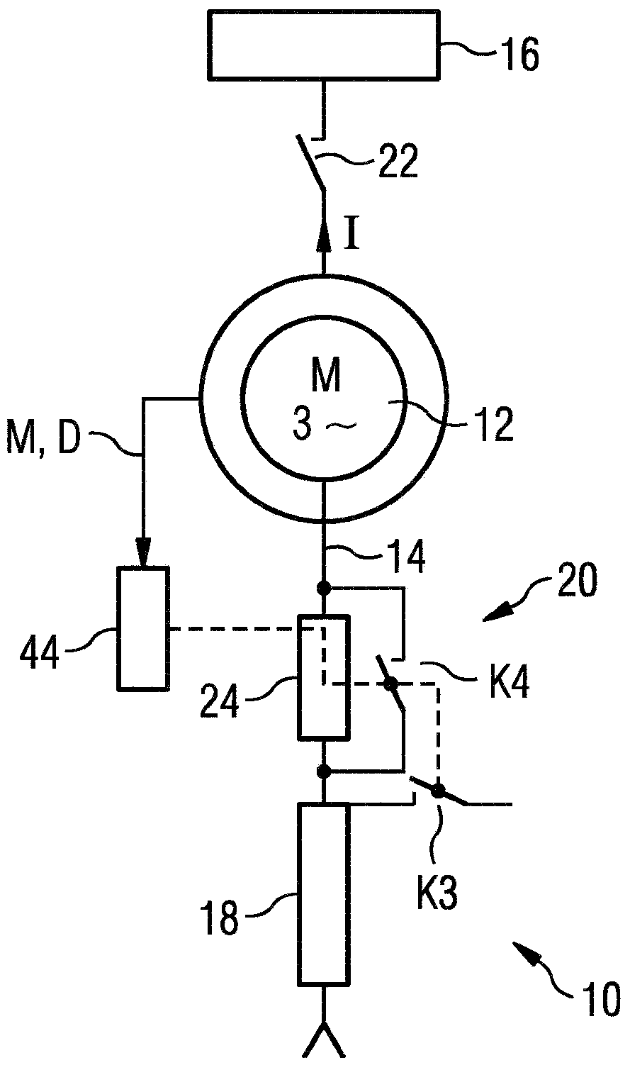
[0030] figure 1 A ball mill 2 is shown which essentially has a housing 4 and a drum 6 arranged rotatably therein. Inside the drum 6 there is the material to be ground, here in the form of ore 8 . Grinding bodies are usually included in the grinding mass, but are not shown separately here. Thus, existing grinding bodies are theoretically included when the concept of ore is used. The ball mill 2 has a drive system 10 comprising an electric motor 12 which drives the drum 6 . The motor is connected to a power supply device 16 through a feeder 14 (see figure 2 ) are connected. The drive current I of the motor 12 flows through the feeder. Drive system 10 additionally includes a resistor 18 in the form of a starting resistor, which is connected into feeder line 14 , and a switching element 20 connected in series with this resistor, which is connected into feeder line 14 .

[0031] figure 2 supplementary shows figure 1 Details of a drive system 10 with a motor 12 and a resis...


PUM


Abstract

A drive system for a ball mill includes a motor with a slip-ring rotor. The motor is assigned a family of characteristics relating the torque of the motor to a further characteristic variable. The family of characteristics has at least two different characteristics, and it includes a switching element that switches over the drive system abruptly between the two characteristics when there is a constant value of the characteristic variable. In a method for operating a ball mill with a drive system, a drum of the ball mill is moved out of a state of rest when the first characteristic is activated. In the event of caking in the drum of the ball mill, it the drum is moved until the caking is in an inclined position. Actuation of the switching element brings about switching over to the second characteristic.

Description

technical field [0001] The invention relates to a drive system for a ball mill and a method of operating a ball mill. Background technique [0002] A ball mill is a device for coarse crushing, fine crushing and the finest crushing or homogenization of ground materials. The device comprises a grinding chamber, usually formed by the interior of a drum which can be turned into rotation, in which the grinding material is comminuted by means of grinding bodies. Ball mills are used in both wet and dry milling. The concept ball mill relates in particular to tumble mills, drum mills and tube mills. In the ball mill, not only spherical grinding bodies are used, but also other forms, such as cylindrical grinding bodies, etc. are used as grinding bodies. [0003] Ball mills are used, for example, in mining enterprises to grind ore. In other manufacturing industries, ceramic materials or material mixtures can be finely ground as the material to be ground for this purpose. Ball mill...

Claims


Application Information

Patent Timeline
Patent Type & Authority Applications(China)
IPC IPC(8): B02C17/24H02P1/34B02C17/18
CPCB02C17/24B02C17/1805H02P1/34B02C25/00H02P25/24
Inventor 马尔藤·霍兰
Owner SIEMENS AG
Why Eureka
Try Eureka