
Method for collaboration application among split type terminals and split type terminals

A split-type, inter-terminal technology, applied in the field of communication, can solve the problems of small memory and no storage of pictures, poor camera pixels, low efficiency, etc., and achieve the effect of convenient and efficient operation and good user experience.

Active Publication Date: 2013-11-06
YULONG COMPUTER TELECOMM SCI (SHENZHEN) CO LTD
View PDF7 Cites 6 Cited by
  • Summary
  • Abstract
  • Description
  • Claims
  • Application Information

AI Technical Summary

Problems solved by technology

For example, the user needs to reply after receiving an MMS message using the sub-phone, but the sub-phone has no camera or the camera pixel is not good, or the image is not stored due to the small memory. At this time, the user can only take out the host, and select or After taking pictures and transferring them to the sub-machine, this operation is inefficient on the one hand, and on the other hand, the user needs to perform multiple operations on the main machine to complete
In addition, after receiving other people's text messages, the sub-machine user needs to set a schedule reminder according to the text message, but due to the limitation of the function module of the sub-machine, no calendar-related functions are added, so the user can only transfer the text message to the main unit or manually set it on the main unit schedule, resulting in inconvenient and efficient user operations and poor user experience
[0003] In summary, there are obviously inconveniences and defects in the actual use of the existing technology, so it is necessary to improve

Method used


Image

  • Method for collaboration application among split type terminals and split type terminals
  • Method for collaboration application among split type terminals and split type terminals
  • Method for collaboration application among split type terminals and split type terminals

Examples


Embodiment Construction

[0068] In order to make the object, technical solution and advantages of the present invention more clear, the present invention will be further described in detail below in conjunction with the accompanying drawings and embodiments. It should be understood that the specific embodiments described here are only used to explain the present invention, not to limit the present invention.

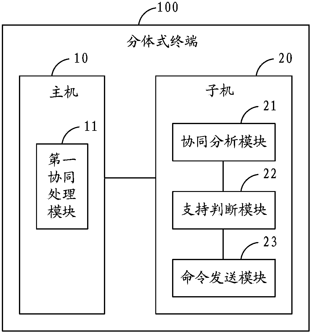
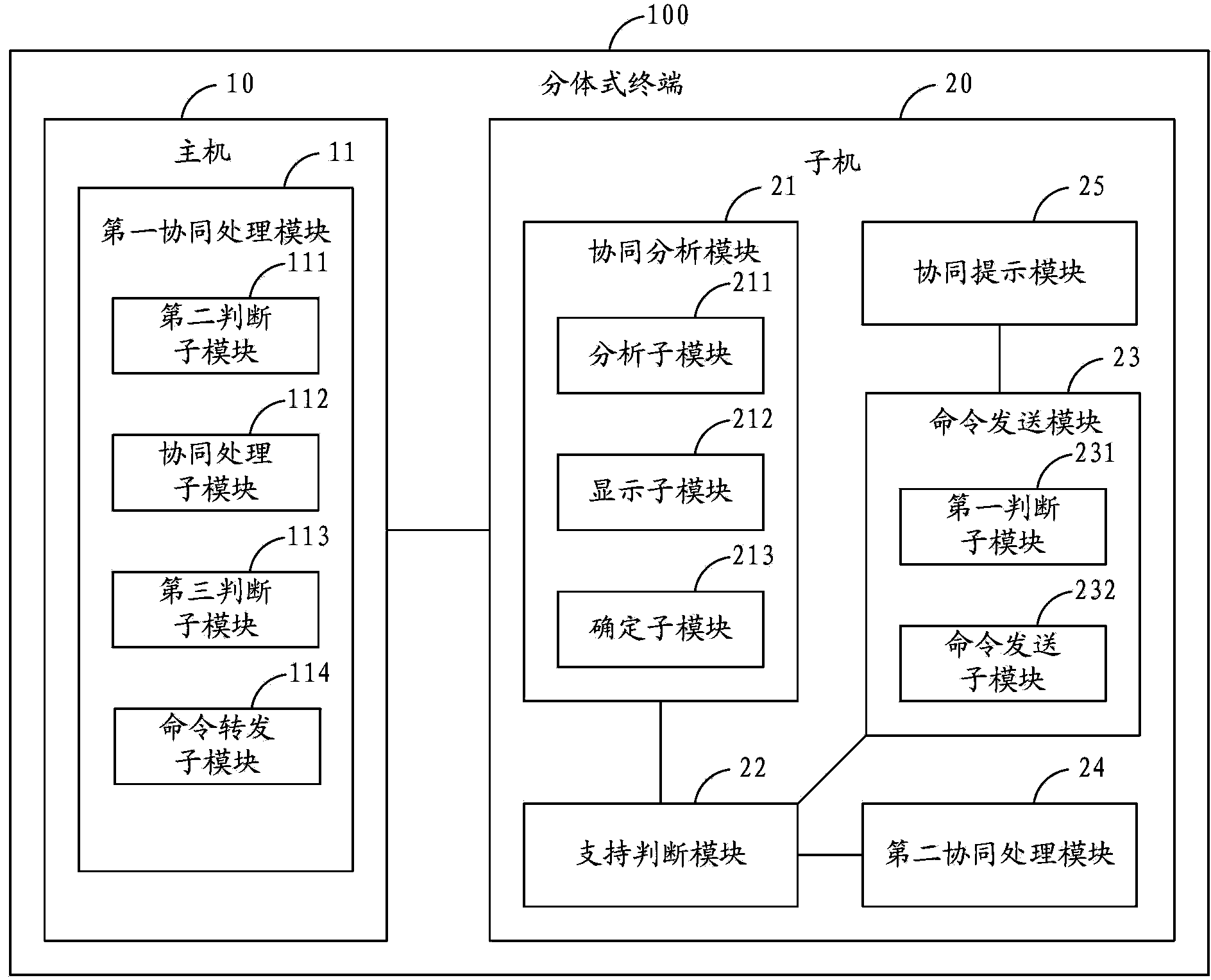
[0069] figure 1 It is a schematic structural diagram of a split terminal according to the present invention, and the split terminal 100 includes a host 10 and at least one slave 20 . The host 10 and the slave 20 can be mobile phones, PDAs (Personal Digital Assistants, personal digital assistants), tablet computers, etc., and the host 10 and slaves 20 can communicate wirelessly through mobile networks, bluetooth, and the like.

[0070] The slave machine 20 includes:

[0071] The collaboration analysis module 21 is configured to analyze the applications requiring collaboration according to the i...


PUM


Abstract

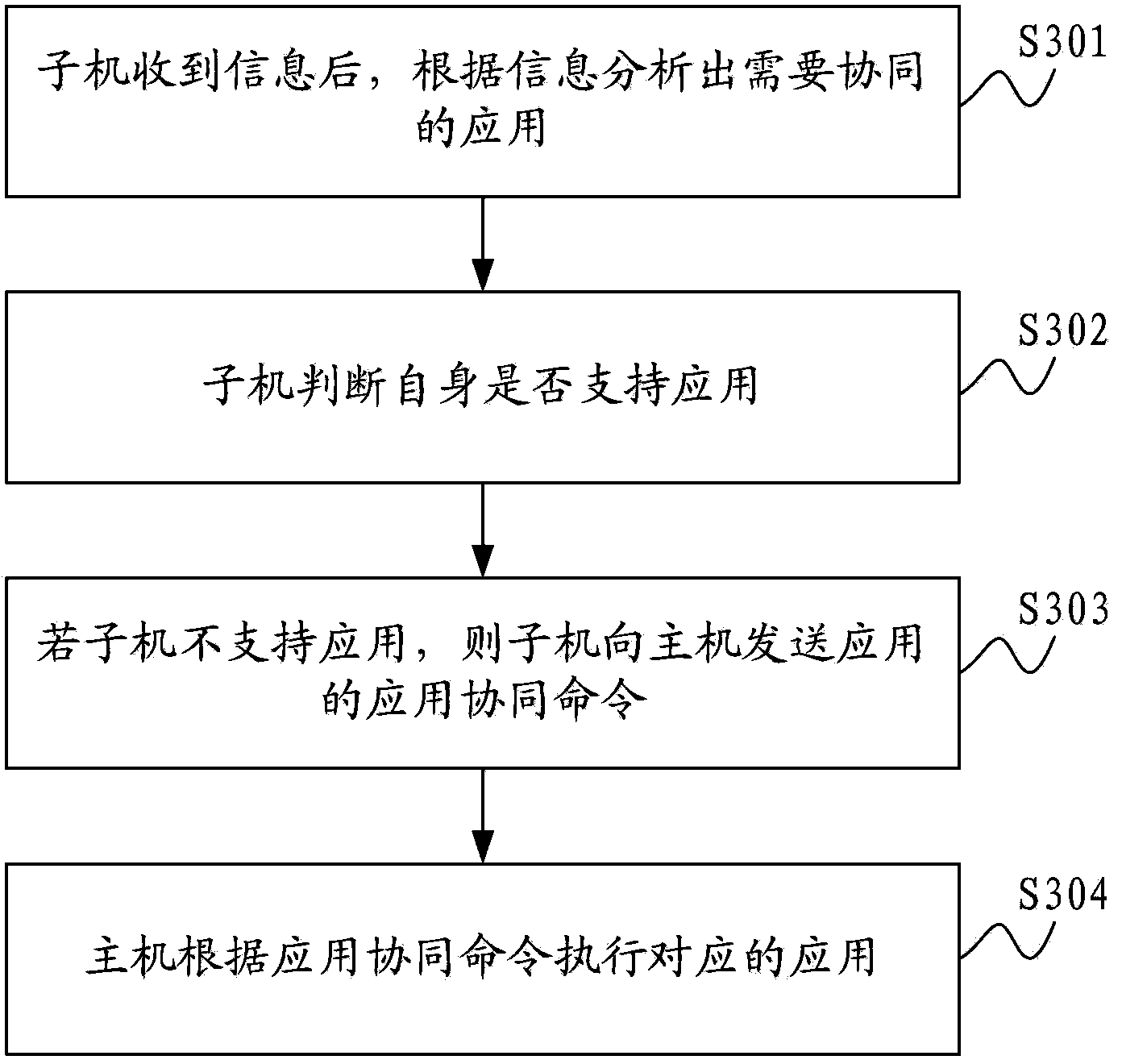
The invention relates to the technical field of communication and provides a method for collaboration application among split type terminals and the split type terminals. Each split type terminal comprises a host computer and at least one sub-computer. The method for the collaboration application among the split type terminals comprises the steps that an application needs to be collaborated is analyzed according to a message after the sub-computer receives the message, whether the sub-computer supports the application is judged by the sub-computer itself, an application collaboration command of the application is sent to the host computer by the sub-computer if the sub-computer does not support the application, and then the application is executed by the host computer according to the application collaboration command. Therefore, the method for the collaboration application among the split type terminals has the advantages that the application collaboration can be achieved among the split type terminals, and user operation can be more convenient and more efficient.

Description

technical field [0001] The present invention relates to the field of communication technology, in particular to a method for application collaboration between split terminals and the split terminals. Background technique [0002] In the prior art, there is a lack of coordinated operation between split terminals. For example, the data interaction between the Bluetooth slave and the host is mainly based on synchronization, and there is a lack of application collaboration between the two. For example, the user needs to reply after receiving an MMS message using the sub-phone, but the sub-phone has no camera or the camera pixel is not good, or there are no pictures stored due to the small memory. At this time, the user can only take out the host and select or After taking pictures and then transferring them to the sub-machine, this operation is inefficient on the one hand, and on the other hand, the user needs to perform multiple operations on the main machine to complete it. I...

Claims


Application Information

Patent Timeline
IPC IPC(8): H04M1/725G06F9/46
Inventor 王旭郭斌李炜
Owner YULONG COMPUTER TELECOMM SCI (SHENZHEN) CO LTD
Learn More