Selector shaft with an open sleeve

A sleeve and switching lever technology, applied in the direction of elements with teeth, belts/chains/gears, mechanical equipment, etc., can solve the problems of expensive manufacturing process, high material cost, high quality of stop sleeve, etc., to save Material and weight, flexible manufacturing process, effect of reducing scrap rates

Active Publication Date: 2013-11-06
SCHAEFFLER TECH AG & CO KG
View PDF9 Cites 8 Cited by
  • Summary
  • Abstract
  • Description
  • Claims
  • Application Information

AI Technical Summary

Problems solved by technology

[0005] The disadvantage of such a stop sleeve is that the half shells have to be shaped very precisely in order to be connected to each other along the interface, for example by laser welding
Compliance with this predetermined condition makes the manufacturing process very expensive
The mass of the stop sleeve is relatively large, and the material cost of manufacturing it is relatively high

Method used


Image

  • Selector shaft with an open sleeve
  • Selector shaft with an open sleeve
  • Selector shaft with an open sleeve

Examples


Embodiment Construction

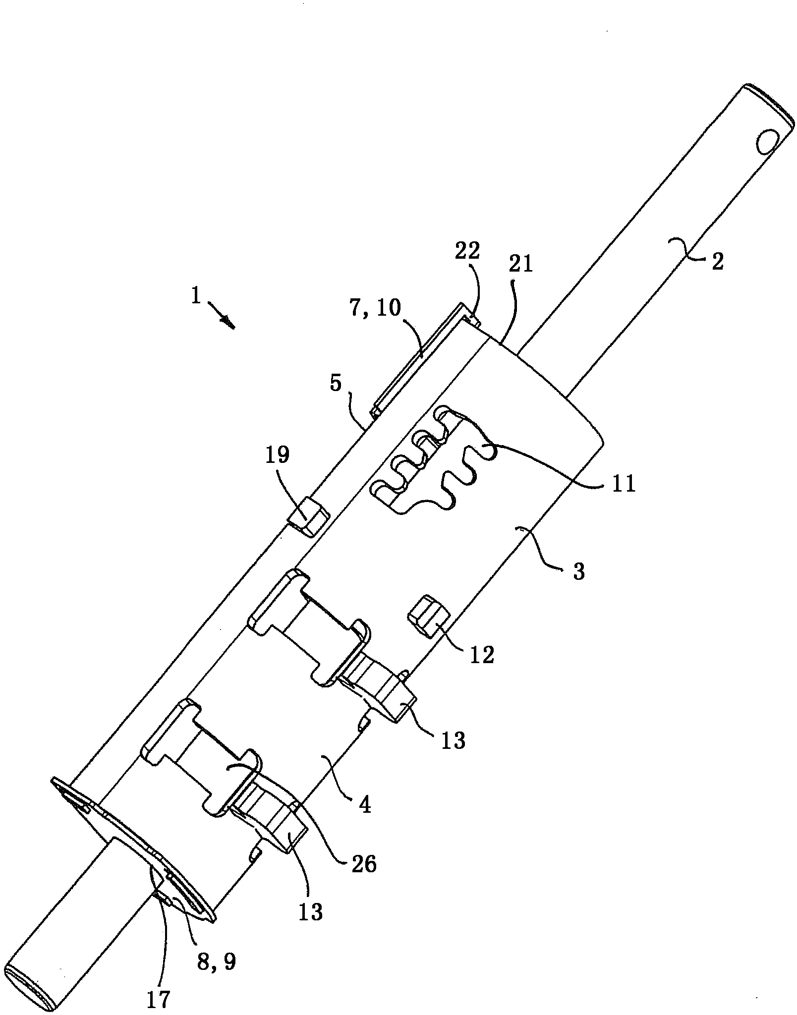
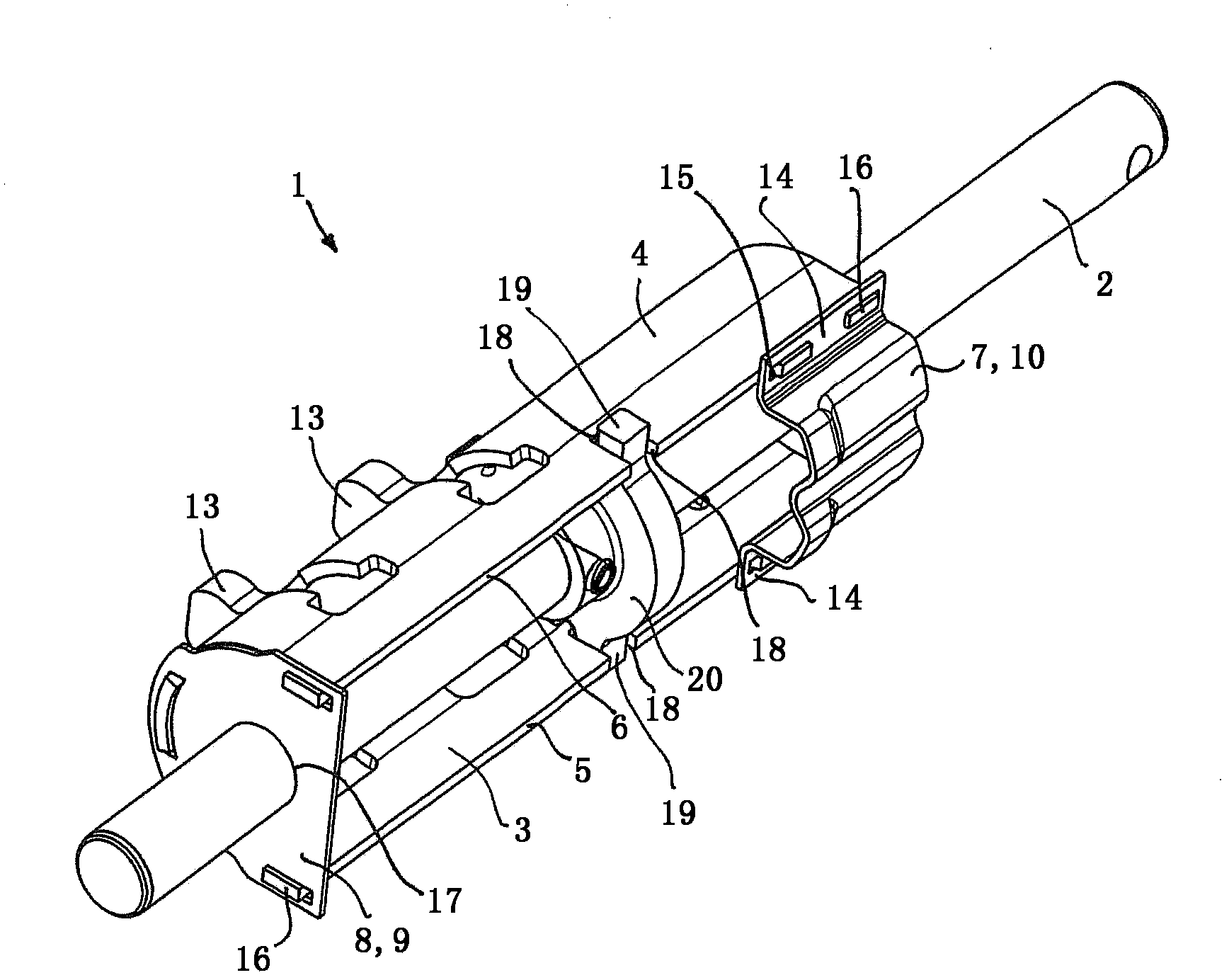
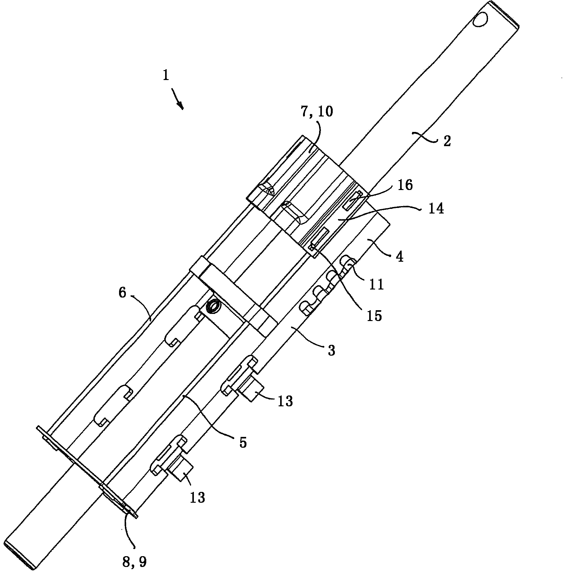
[0029] Figure 1 to Figure 3 A switching device 1 is shown which comprises a solid switching lever 2 and a sleeve 3 with a circular cross section. The sleeve 3 is assembled from a half shell 4 and two connecting parts 7 , 8 . The half shells 4 are produced from sheet steel parts cut to length from a strip. The desired outer contour with possibly required projections 16 or other projecting elements can be stamped into the sheet metal immediately after cutting to length. Alternatively, the corresponding sheet metal parts are stamped together from the strip. While still in the flat state, recesses, such as switching guides 11 for engaging pins (not shown), are punched into the sheet metal, and shapings, such as stops 12 , are introduced into the sheet metal. Subsequently, the sheet metal part is cold deformed to form the half shell 4 . The outer contour of the half shell 4 is U-shaped with two sides 5 and 6 , which are oriented parallel to one another. Switching fingers 13 a...


PUM


Abstract

A selector device (1) of a motor vehicle variable-speed transmission with a sliding selector shaft (2) and a sleeve (3) arranged on the sliding selector shaft (2), wherein the sleeve (3) has a half shell (4) with two limbs (5, 6) and one or more connecting parts (7, 8) which in each case connect the limbs (5, 6) to each other, wherein the connecting part or connecting parts (7, 8) is or are axially shorter than the half shell (4).

Description

technical field [0001] The invention relates to a shifting device of a motor vehicle transmission with a shift lever and a sleeve arranged on the shift lever, wherein the sleeve has a half shell and one or more connecting parts, the half shell has two sides part, the connecting part correspondingly connects the side parts to each other. Furthermore, the invention relates to a method for producing such a sleeve. Background technique [0002] A shifting lever as part of a shifting device is a movable shifting element in a shifting transmission which transmits a shifting movement initiated by the driver or an actuator to other downstream shifting elements. There is usually a sleeve on the switching lever, on which other functional components, such as locking contours, switching fingers or stops, are arranged. These further functional components then do not need to be arranged directly on the relatively small switching lever surface, which simplifies the arrangement. Plus the...

Claims


Application Information

Patent Timeline
Patent Type & Authority Applications(China)
IPC IPC(8): F16H63/30F16H63/38
CPCF16H63/38F16H63/30F16H2063/3076F16H2061/242
Inventor 克劳斯·克拉默约亨·洛菲尔曼
Owner SCHAEFFLER TECH AG & CO KG
Why Eureka
Try Eureka