Converter station with diode rectifier

A technology of diode rectifier and converter station, applied in the field of converter station, can solve the problems of high manufacturing cost, occupying space, heavy converter station, etc.

Active Publication Date: 2018-03-27
SIEMENS ENERGY GLOBAL GMBH CO & KG
View PDF6 Cites 0 Cited by
  • Summary
  • Abstract
  • Description
  • Claims
  • Application Information

AI Technical Summary

Problems solved by technology

This component however makes the converter station mentioned at the outset heavier and more space-consuming, resulting in high manufacturing costs especially when used at sea

Method used


Image

  • Converter station with diode rectifier
  • Converter station with diode rectifier
  • Converter station with diode rectifier

Examples


Embodiment Construction

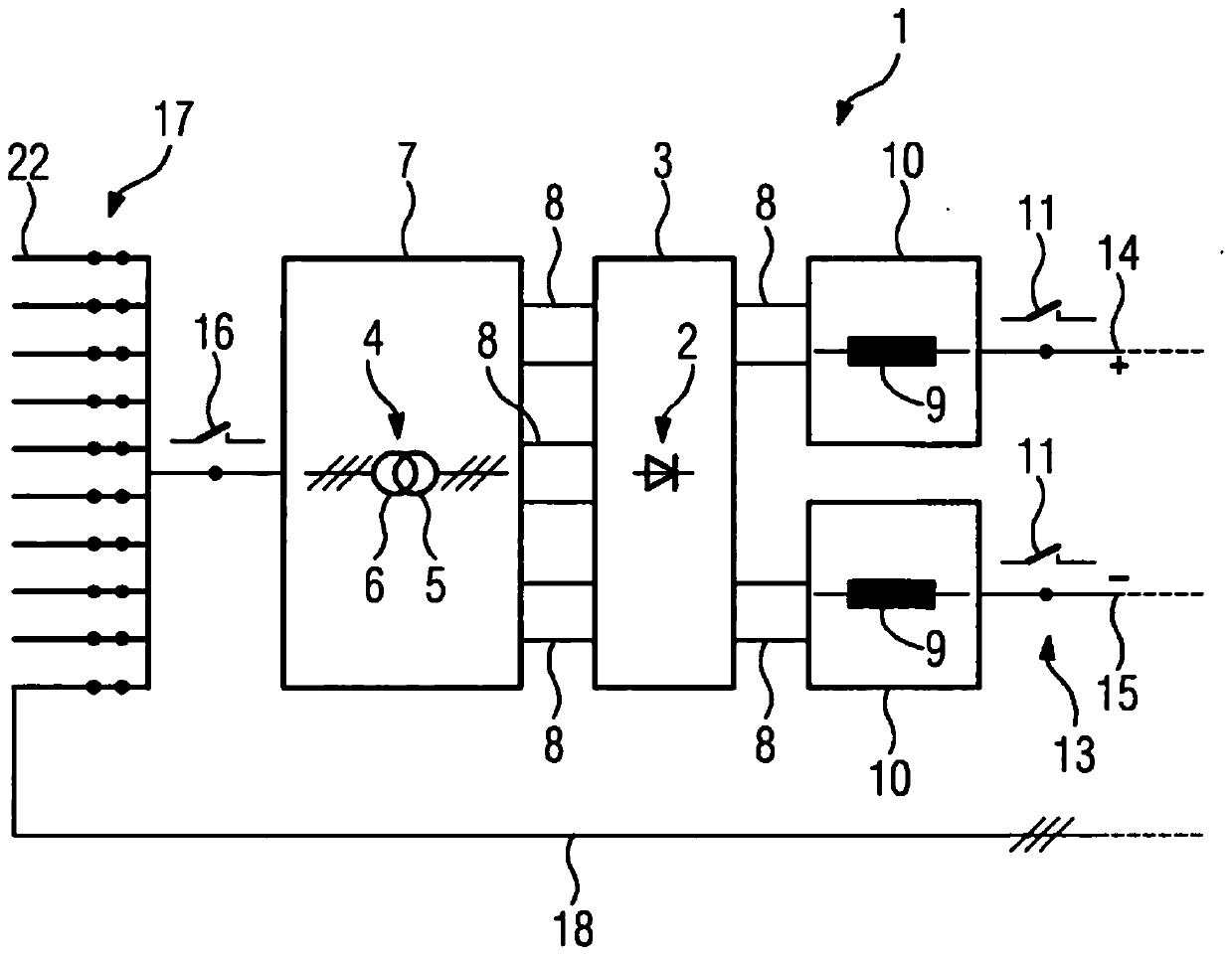
[0034] figure 1 An embodiment of a converter station 1 according to the invention is shown having a diode rectifier 2 arranged in an encapsulation housing 3 filled with insulating material. insulating material in figure 1 The example shown is insulating oil. Furthermore, the converter station 1 comprises a transformer 4 having a primary winding 5 and a secondary winding 6 which are inductively coupled to one another. The transformer 4 is arranged in an encapsulation case 7 filled with the same insulating oil. A hollow-cylindrical supply line 8 , likewise filled with insulating oil, is used for routing the phase conductors connected on the AC voltage side between the transformer 4 and the converter 2 . The encapsulation housings 3 , 7 are at ground potential.

[0035] The converter station 1 also has two smoothing inductors 9 , which are each connected to the two DC voltage connections of the diode rectifier 2 . Each smoothing inductor 9 is arranged in a separate encapsula...


PUM


Abstract

The invention relates to a converter station (1) for transmitting electric power, having a diode rectifier (2), the diode rectifier having a DC voltage connection and an AC voltage connection; and at least one transformer connected to the AC voltage connection (4) In order to make the converter station as compact as possible, it is proposed that the diode rectifier (2) is arranged in insulating material.

Description

technical field [0001] The invention relates to a converter station for the transmission of electric power, comprising: a converter having a direct voltage connection and an alternating voltage connection; and at least one transformer connected to the alternating voltage connection, wherein Transformers and converters are arranged in insulating material. Background technique [0002] Such a converter station is known, for example, from "Windpower plant control for the connection to multiterminal HVDC links" by S. Bernal-Perez et al., IEEE, 2012, p. 2873. A device is disclosed there in which a diode rectifier is connected on the DC voltage side to a DC voltage intermediate circuit. The direct voltage intermediate circuit runs between two voltage source converters, also called "voltage source converters (VSC)" in English. The diode rectifier is connected to the wind farm through the transformer and the AC grid. Furthermore, a filter unit arranged on the AC voltage side of t...

Claims


Application Information

Patent Timeline
Patent Type & Authority Patents(China)
IPC IPC(8): H02M7/00H02M7/10
CPCH02M7/003H02M7/106H02M1/143H02M7/08H02M7/17H05K5/067
Inventor J.多恩D.埃尔金T.哈默H-J.纳克P.门克R.舒斯特
Owner SIEMENS ENERGY GLOBAL GMBH CO & KG
Why Eureka
Try Eureka