Method, computer program, and apparatus for adapting an estimator for use in a microscope

Pending Publication Date: 2022-02-10
ABBERIOR INSTR GMBH
View PDF0 Cites 0 Cited by
  • Summary
  • Abstract
  • Description
  • Claims
  • Application Information

AI Technical Summary

Benefits of technology

The invention is about a method to estimate the location of an object in real-time while compensating for background noise. This enables unbiased localization and helps to assess the quality of the measurements. The method uses a background estimation to remove bias from the estimator, which allows for better use of available photons and unbiased tracking of molecules. Additionally, by keeping the distance between scanning positions between 10% and 50% of the excitation wavelength, dark spots that could potentially arise from the donut zero can be prevented.

Problems solved by technology

Thus, injecting” or targeting a reference coordinate in the sample shifts the burden of requiring many fluorescence photons for localization to the inexhaustible number of photons in the donut-shaped excitation beam.
The approach is complicated by the fact that in order to arrive at an unbiased result, i.e. a result without a systematic error, specific experimental conditions must be considered, such as the spatial intensity distribution of the donut and the signal-to-noise ratio.
So far, these conditions have been taken into account by time-consuming post-processing of the localization data.

Method used


Image

  • Method, computer program, and apparatus for adapting an estimator for use in a microscope
  • Method, computer program, and apparatus for adapting an estimator for use in a microscope
  • Method, computer program, and apparatus for adapting an estimator for use in a microscope

Examples


first embodiment

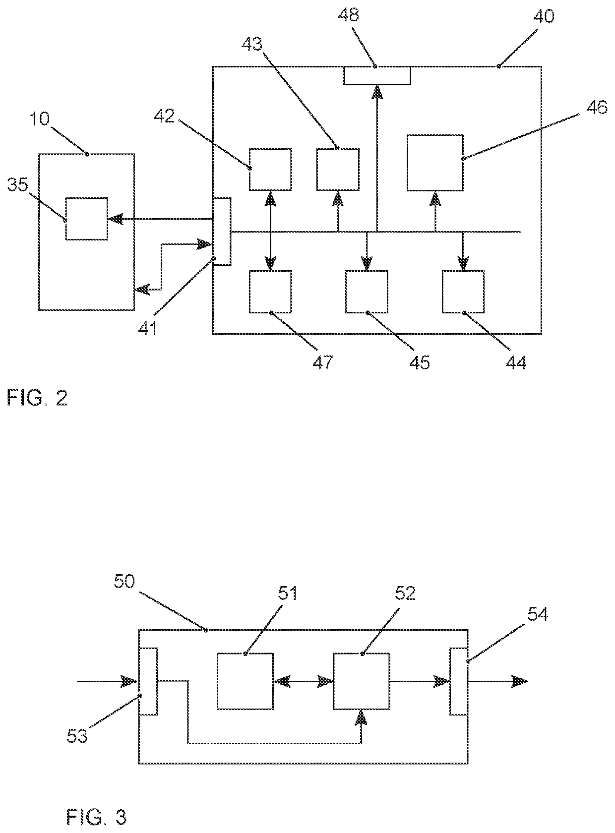
[0088]FIG. 2 schematically illustrates a block diagram of an apparatus 40 according to the invention for adapting an estimator 35 for use in a microscope 10 for estimating a position of an emitter in a sample. For example, the estimator 35 may be a least-mean-squared estimator. The apparatus 40 has an interface 41 for exchanging data with components of the microscope 10. An illumination means 42 is configured to illuminate the sample with light at one or more sets of probe positions, e.g. by instructing a light source and position control elements of the microscope accordingly. Advantageously, the sets of probe positions are illuminated S1 multiple times. Opposing probe positions of a set of probe positions may be illuminated S1 in sequential pairs. Preferably, a set of probe positions comprises three or more probe positions, which are arranged rotationally symmetric on a circle. An acquisition means 43 is configured to acquire fluorescence photons for the sets of probe positions, e...

second embodiment

[0090]A block diagram of an apparatus 50 according to the invention for adapting an estimator for use in a microscope for estimating a position of an emitter in a sample is illustrated in FIG. 3. The apparatus 50 comprises a processing device 51 and a memory device 52. For example, the apparatus 50 may be a computer, an electronic control unit or an embedded system. The memory device 52 has stored instructions that, when executed by the processing device 51, cause the apparatus 50 to perform steps according to one of the described methods. The instructions stored in the memory device 52 thus tangibly embody a program of instructions executable by the processing device 51 to perform program steps as described herein according to the present principles. The apparatus 50 has an input 53 for receiving data. Data generated by the processing device 51 are made available via an output 54. In addition, such data may be stored in the memory device 52. The input 53 and the output 54 may be co...


PUM


Abstract

The present invention is related to a method, a computer program, and apparatus for adapting an estimator for use in a microscope for estimating a position of an emitter in a sample based on a method, in which the sample is illuminated with light at one or more sets of probe positions and fluorescence photons are acquired for the sets of probe positions. The invention is further related to a microscope, which makes use of such a method or apparatus. The sample is illuminated with light at one or more sets of probe positions and fluorescence photons are acquired for the sets of probe positions. Photon counts of the acquired photons are then added to vectors of photon counts or sums of photon counts are determined for the sets of probe positions. A value representative of background noise is determined and used for adapting the estimator in real-time.

Description

RELATED APPLICATION[0001]This application claims benefit of EP Patent Application No. 20190122.0 filed Aug. 7, 2020, which is incorporated herein by reference.BACKGROUND OF THE INVENTIONa. Field of the Invention[0002]The present invention is related to a method, a computer program, and an apparatus for adapting an estimator for use in a microscope for estimating a position of an emitter in a sample. The invention is further related to a microscope, which makes use of such a method or apparatus.b. Description of the Prior Art[0003]Fluorescence microscopy has experienced a second resolution boost due to the synergistic combination of the specific strengths of the coordinate-targeted super-resolution family represented by STED (STimulated Emission Depletion) and RESOLFT (REversible Saturable OpticaL Fluorescence Transitions) and its coordinate-stochastic counterpart comprising PALM (PhotoActivated Localization Microscopy) / STORM (STochastic Optical Reconstruction Microscopy) and PAINT (...

Claims


Application Information

Patent Timeline
IPC IPC(8): G01N21/64G02B21/16
CPCG01N21/6458G02B21/16G02B21/0076G02B21/008G02B21/0072G06T7/0014G06T2207/10064
Inventor SCHMIDT, ROMAN
Owner ABBERIOR INSTR GMBH
Why Eureka
Try Eureka