
Fan coil temperature controller for hotels

A technology of fan coil unit and thermostat, applied in heating and ventilation control systems, applications, household heating and other directions, can solve the problems of low usage, the fan coil unit cannot work normally, and the guests feel uncomfortable, etc. The effect of promoting energy saving and emission reduction

Inactive Publication Date: 2013-11-13
南京东创节能技术有限公司
View PDF3 Cites 1 Cited by
  • Summary
  • Abstract
  • Description
  • Claims
  • Application Information

AI Technical Summary

Problems solved by technology

[0005] (2) At present, some products on the market have a sleep function, but the setting of this function needs to be realized by operating the buttons on the controller panel (generally, guests will not actively set the sleep state before falling asleep);
[0006] (3) The working power of all fan coil units is obtained through the door card, and the fan coil unit cannot work normally when the guest leaves without the card
[0008] (1) Most of the guests will not touch the sleep button before going to sleep, and the actual use of this function is not high;
[0009] (2) Since the fan coil unit in the hotel cannot be started until the guest gets the room card and enters the room to insert the card, when the guest enters the room, the temperature is high (summer) or the temperature is low (winter), and the guest will feel uncomfortable for a period of time. comfortable;
[0010] (3) When the guest dials the card and goes out for a period of time and enters the room again, he will face the problem described in (2) again

Method used


Image

  • Fan coil temperature controller for hotels
  • Fan coil temperature controller for hotels

Examples


Embodiment Construction

[0028] The present invention will be further described below in conjunction with the accompanying drawings and embodiments.

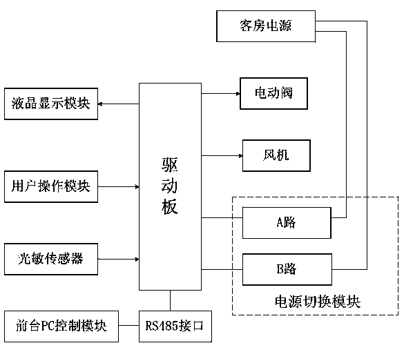
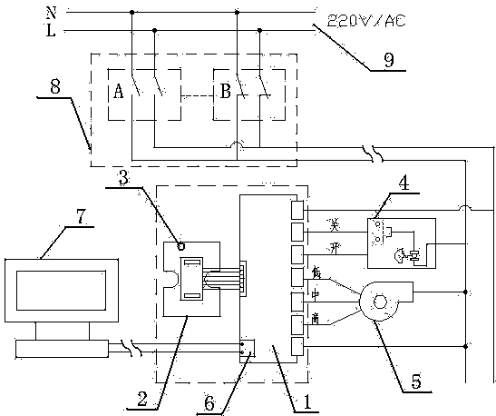
[0029] Such as figure 1 and figure 2 As shown, a fan coil thermostat for hotels, which includes a user panel 2 (including a liquid crystal display module and a user operation module), a drive board 1, an electric valve 4, a fan 5, a photosensitive sensor 3, an RS485 interface 6, and a front desk The PC control module 7 and the power switching module 8 are connected to the signal output end of the user operation module with the signal input end of the driver board 1; the signal output ends of the driver board 1 are respectively connected with the signal input ends of the liquid crystal display module. The switch lines of the electric valve 4 are respectively connected with the signal output terminals of the drive board 1; the low, medium and high-grade lines of the fan 5 are respectively connected with the signal output terminals of the drive board 1; ...


PUM


Abstract

The invention discloses a fan coil temperature controller for hotels. The fan coil temperature controller comprises a liquid crystal display module, a user operation module, a driving board, an electric valve, a fan, a photosensitive sensor, an RS485 interface, a front desk PC (Personal Computer) control module, guest room power supplies and a power switching module, wherein a signal output end of the user operation module is connected with a signal input end of the driving board; a signal output end of the driving board is connected with signal input ends of the liquid crystal display module, the electric valve and the fan respectively; a signal output end of the photosensitive sensor is connected with the signal input end of the driving board; the front desk PC control module is connected with the driving board through the RS485 interface; the guest room power supplies are connected with the power input ends of the driving board through the power switching module respectively; and the power switching module comprises two paths A and B. The fan coil temperature controller system of the structure meets the requirements of guests for comfort and also guarantees the sleep quality and the health of the guests; and meanwhile, the requirements for energy conservation and safety are met by the structure of the double-loop switch.

Description

technical field [0001] The invention relates to the field of fan coil thermostats, in particular to a fan coil thermostat for hotels. Background technique [0002] The fan coil thermostat is suitable for central air-conditioning temperature control in industrial, commercial and family rooms. The thermostat is divided into mechanical thermostat and electronic thermostat. By comparing the indoor temperature with the set temperature, the fan coil unit and electric valve or electric damper at the end of the air conditioning system are controlled. To achieve the purpose of adjusting indoor temperature, improving environmental comfort and saving energy. [0003] At present, the basic functions of fan coil thermostats used in hotels include: [0004] (1) According to the indoor temperature and the temperature set by the customer on the thermostat panel, automatically turn on the fan of the fan coil unit (select the high, medium and low air volume of the fan coil unit at the same...

Claims


Application Information

Patent Timeline
Patent Type & Authority Applications(China)
IPC IPC(8): F24F11/00
Inventor 罗旭
Owner 南京东创节能技术有限公司
Learn More