Separated type weight balancing device

A counterweight device and separate technology, which is applied in the field of separate weight counterweight devices, can solve the problems of difficult to ensure the mass balance of the counterweight, difficulty, difficulty in installation and transportation, etc., and achieve convenient and fast weight coordination and mass balance rate Improvement, the effect that is convenient for adjustment of the weight

Active Publication Date: 2013-11-13
HARBIN INST OF TECH
View PDF5 Cites 9 Cited by
  • Summary
  • Abstract
  • Description
  • Claims
  • Application Information

AI Technical Summary

Problems solved by technology

[0003] The purpose of the present invention is to solve the problem that the existing counterweight device is difficult to ensure the mass balance of the counterweight, and when the mass is large, it is difficult to install and transport, and to provide a separate weight counterweight device

Method used


Image

  • Separated type weight balancing device
  • Separated type weight balancing device

Examples


specific Embodiment approach 1

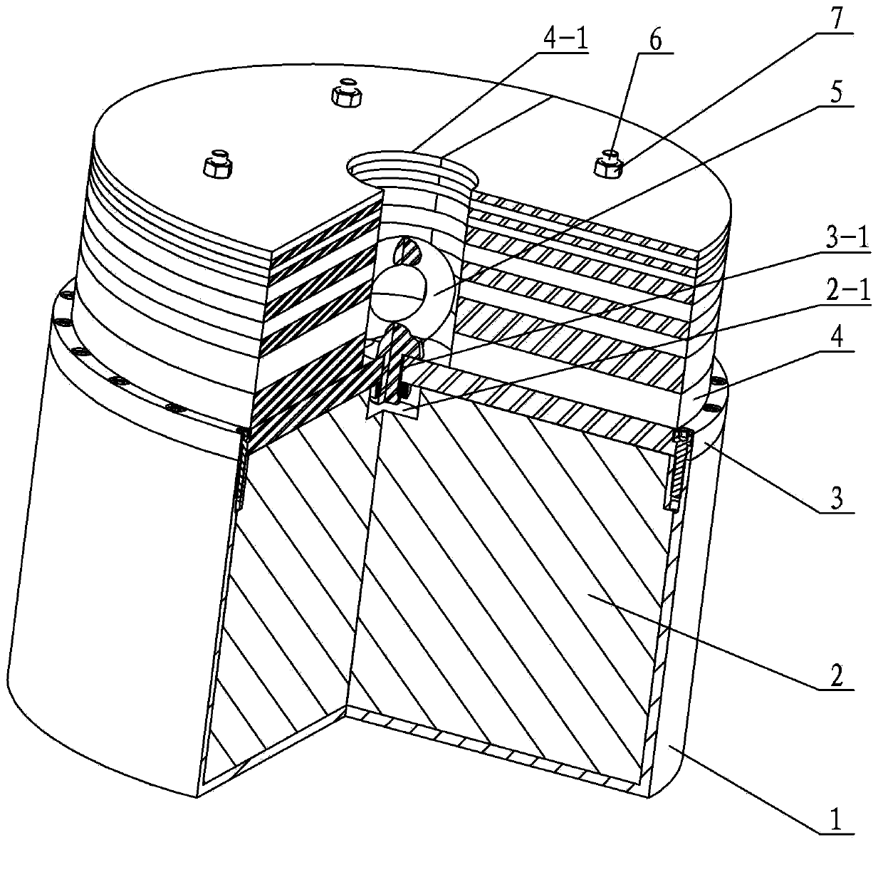
[0011] Specific implementation mode one: combine figure 1 with figure 2 Describe this embodiment, this embodiment includes counterweight container 1, counterweight lead core 2, counterweight container cover 3, eyebolt screw 5, four fixing studs 6, four fixing nuts 7 and several counterweight weights 4 , the counterweight lead core 2 is installed in the counterweight container 1, the counterweight container cover 3 is installed on the upper end of the counterweight lead core 2 and fixed with the counterweight container 1 with connecting elements, and several counterweight weights 4 are stacked sequentially from bottom to top Placed on the upper end of the counterweight lead core 2, four fixed studs 6 are evenly distributed on the upper end surface of the counterweight container cover 3 along the same circumference, and the lower end of each fixed stud 6 is threadedly connected with the counterweight container cover 3. The upper end of a fixed stud 6 passes through several cou...

specific Embodiment approach 2

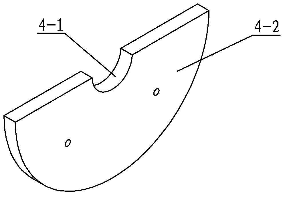
[0012] Specific implementation mode two: combination figure 1 This embodiment is described. In this embodiment, two groups of semicircular counterweights 4 are formed into a complete circle with the eye screw 5 as the center, and are stacked on the upper end surface of the counterweight container cover 3. Each The semicircular joints of the counter weights 4 of two adjacent layers are staggered. Such a design can ensure the overall stability of the weight, and is also convenient for the disassembly of the counter weight 4. Since each weight is divided into two semicircles, the weight of the transport unit is also reduced. Other components and connections are the same as those in the first embodiment.

specific Embodiment approach 3

[0013] Specific implementation mode three: combination figure 1 To illustrate this embodiment, in this embodiment, the semicircular joints of each adjacent two layers of counterweights 4 are staggered by 90°, so that the design can ensure the overall stability of the counterweights and facilitate the disassembly of the counterweights 4 , since each weight is divided into two semicircles, the weight of the transport unit is also reduced. The other components and connections are the same as those in the second embodiment.


PUM


Abstract

The invention discloses a separated type weight balancing device, relates to a weight balancing device, and aims to solve problems that the balance weight mass is difficult to guarantee by means of a conventional weight balancing device, and a balance weight is difficult to mount and transport when the mass is large. A balance weight lead core is mounted in a balance weight container, a balance weight container cover is mounted at the upper end of the balance weight lead core, and a plurality of balance weights are stacked at the upper end of the balance weight lead core from bottom to top sequentially; four fixed studs are distributed and arranged on the upper end surface of the balance weight container cover along the same circumference, the lower end of each fixed stud is in threaded connection with the balance weight container cover, and the upper end of each fixed stud penetrates through a plurality of balance weights to be in threaded connection with fixing nuts; a threaded hole is formed in the center of the balance weight container cover, and a groove rightly opposite to the threaded hole is formed in the balance weight lead core; two semi-circle weights of each balance weight form a round plate structure, and a central hole is formed in the center of the round plate; and a lifting bolt is arranged in the central hole and in threaded connection with the threaded hole. The separated type weight balancing device is used for increasing the weight of a mechanism so as to keep balance of the mechanism.

Description

technical field [0001] The invention relates to a weight counterweight device, in particular to a separate weight counterweight device. Background technique [0002] At present, the counterweight device is mainly used to increase the weight of the mechanism itself, so as to maintain the balance of the mechanism itself. The application of the counterweight is very extensive, from large-scale projects, such as cranes, elevators, etc., to small experimental equipment, such as balances, Self-balancing platforms, etc., counterweights are one of the essential workpieces. Due to its wide practicability, the shape and material of the counterweight are different in different occasions. In large-scale projects, the counterweight device mainly appears in the shape of a cube, such as a concave counterweight iron, a rectangular counterweight iron, or a rectangular structure with a square top surface of the ship and elevator counterweight iron; The circular notch iron is the main one. ...

Claims


Application Information

Patent Timeline
Patent Type & Authority Applications(China)
IPC IPC(8): G01M1/32
Inventor 赵杰朱延河闫继宏刘刚峰唐术锋
Owner HARBIN INST OF TECH
Why Eureka
Try Eureka