
Brake System having an Electric Servo Brake

a technology of servo brakes and brake systems, which is applied in the direction of brake systems, brake components, braking components, etc., can solve the problems of negative effect of kinematic chain reliability up to the master cylinder

Inactive Publication Date: 2016-03-24
ROBERT BOSCH GMBH
View PDF7 Cites 2 Cited by
  • Summary
  • Abstract
  • Description
  • Claims
  • Application Information

AI Technical Summary

Benefits of technology

The present invention aims to improve the brake system of vehicles that use a master cylinder and an electric servo brake. The invention aims to prevent the play of two transmissions with gear racks from affecting the guidance of the push rod. The assembly also guarantees a balanced distribution of loads between the two gear racks. The design features of the lever and carrier ensure that the reaction disk is pushed perfectly by a force oriented along the axis of the system. These features prevent the resultant of forces transmitted from the lever to the carrier from having even slight transverse components. Overall, the invention improves the performance and efficiency of the brake system.

Problems solved by technology

However, this system for transmitting the movement of the electric motor to the push rod of the master cylinder has the disadvantage of not taking into account differences in play, even very slight, between the two symmetrical drive mechanisms containing the gear racks, so that the carrier of the reaction disk is almost necessarily arranged obliquely since, in practice, the two gear racks do not advance strictly equally; the reaction disk is positioned obliquely and this has a negative effect on the reliability of the kinematic chain up to the master cylinder.

Method used


Image

  • Brake System having an Electric Servo Brake
  • Brake System having an Electric Servo Brake
  • Brake System having an Electric Servo Brake

Examples


Embodiment Construction

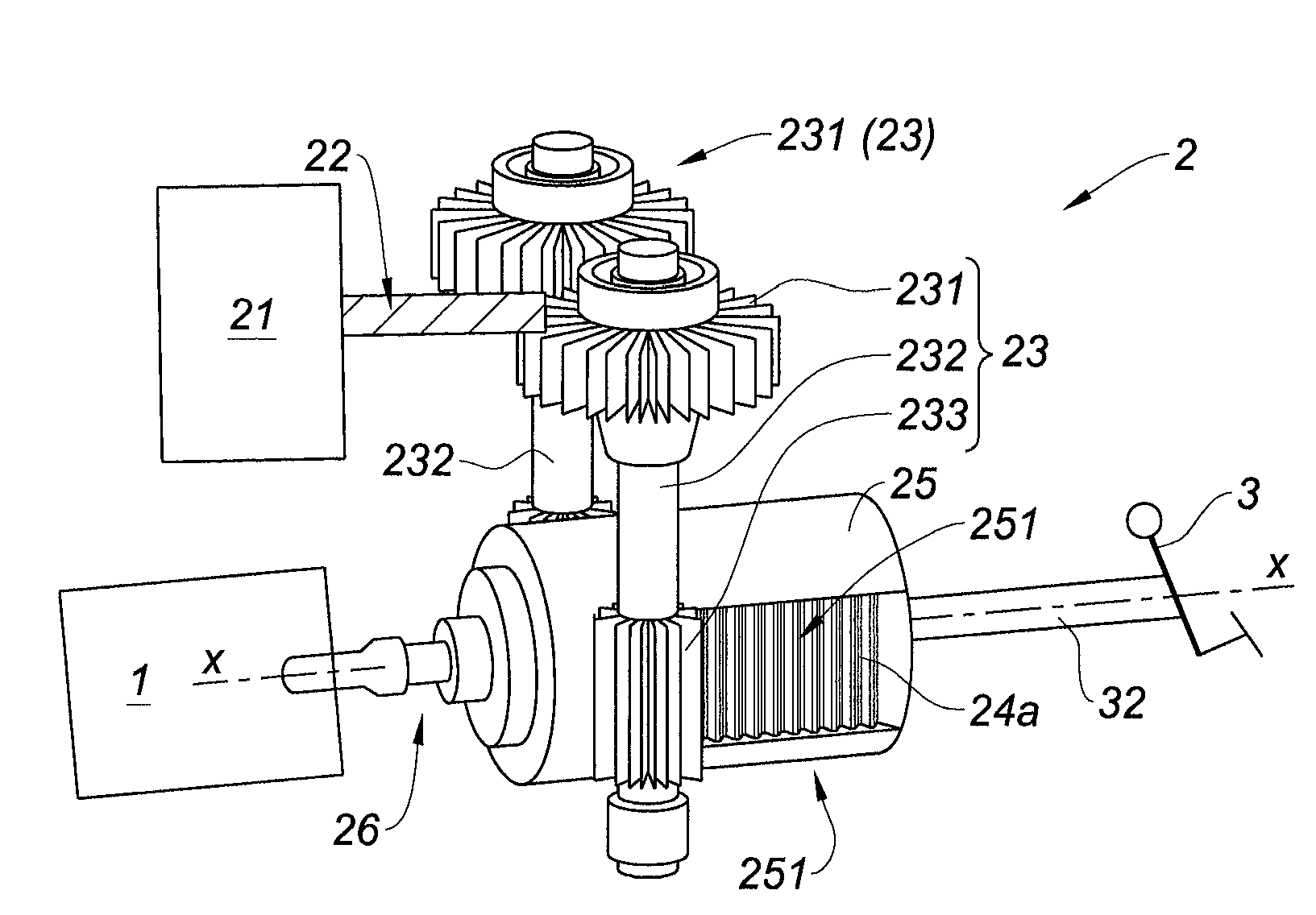
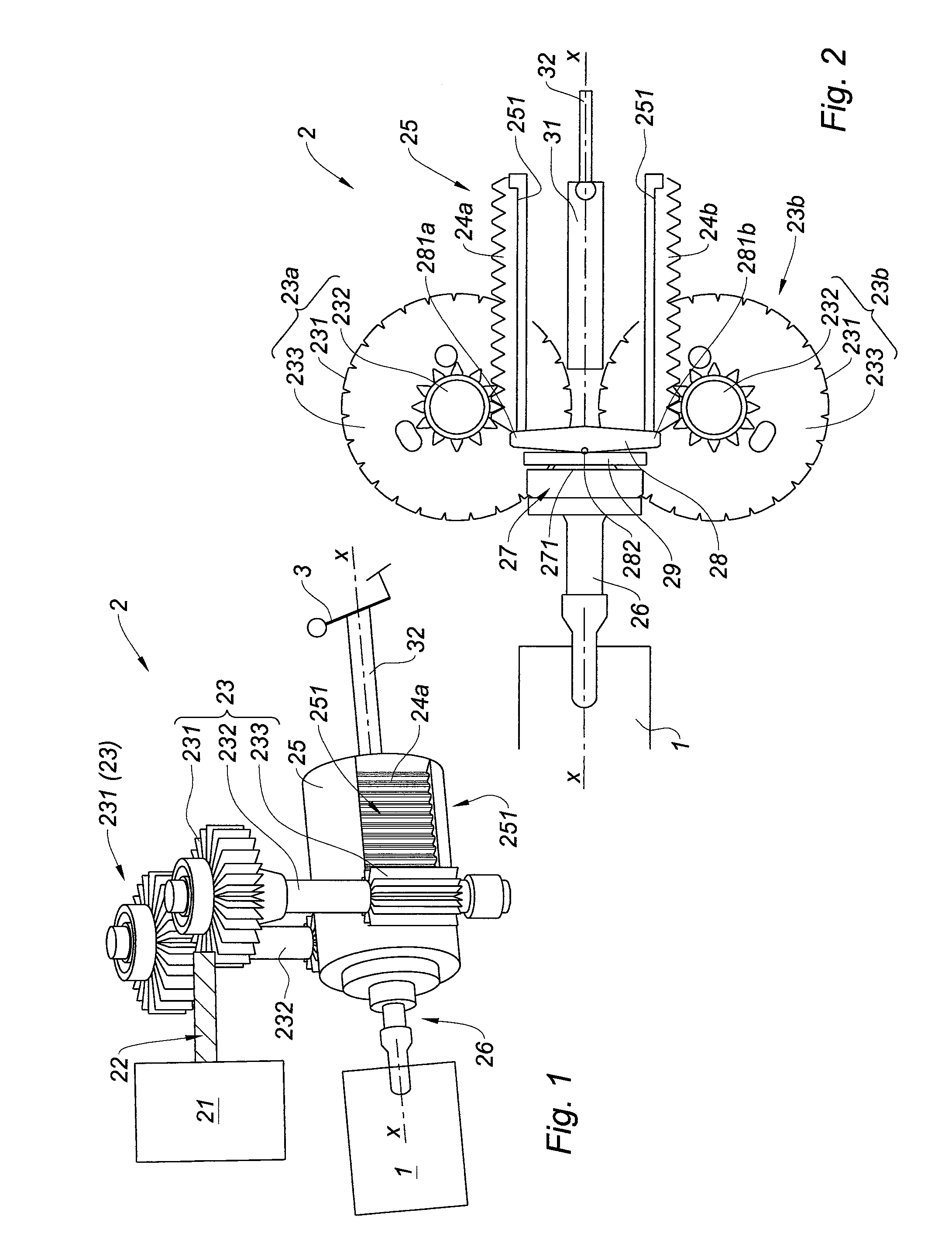
[0024]FIG. 1 shows an overall view of a brake system with master cylinder 1 and electric servo brake 2 according to the invention, wherein the master cylinder 1 and the operating pedal 3 are indicated highly diagrammatically.

[0025]The electric servo brake 2 consists of an electric motor 21, the output shaft of which carries a screw 22 in order to transmit the torque of the motor symmetrically through two transmissions 23a, 23b, symmetrical relative to the axis xx of the brake system (master cylinder and electric servo brake).

[0026]The brake pedal 3 is on the right in the figure (back) and the master cylinder 1 is on the left in the figure (front). The transmissions 23a, 23b of the electric motor consist of two helical gears 231, each carried on a shaft 232 which is provided with a respective spur gear 233 that cooperates with a respective gear rack 24a, 24b. The two gear racks 24a, 24b (only one of which can be seen in FIG. 1) are accommodated sliding in guides 251 of the body 25 of...


PUM


Abstract

A brake system includes a master cylinder, an electric servo brake, and an electric motor. The electric motor drives a screw that engages a pair of helical gears which are each mounted on a respective shaft. Each shaft further mounts a gear that meshes with a respective gear rack. The electric servo brake includes a body that defines rails which guide the gear racks. A lever is supported on each end by one of the gear racks, and is connected to a support via a pivot point. The support lies flat against a side of a reaction disk that lies against a push rod that actuates the master cylinder.

Description

AREA OF THE INVENTION[0001]The present invention relates to a brake system comprising a master cylinder and an electric servo brake which contains:[0002]an electric motor driving a screw that engages in twin helical gears which are each carried by a shaft provided with a gear wheel, which cooperates with a gear rack of a pair of gear racks diametrically opposed relative to the axis xx of the electric servo brake, which is also that of the master cylinder,[0003]wherein the two gear racks slide the push rod which acts on the master cylinder via the reaction disk, on which the control rod can press directly via the plunger.PRIOR ART[0004]Brake systems comprising a master cylinder and an electric servo brake, with transmission of the movement of the electric motor to the push rod of the master cylinder by two mechanisms, symmetrical relative to the axis (xx) of the system, for transmitting the movement of the electric motor to the push rod, are known in various forms.[0005]Thus a known ...

Claims


Application Information

Patent Timeline
Patent Type & Authority Applications(United States)
IPC IPC(8): B60T13/74
CPCB60T13/745F16H19/04
Inventor CAGNAC, BASTIEN
Owner ROBERT BOSCH GMBH
Learn More