A kind of impregnation method of particulate carrier

A carrier and particle technology, applied in chemical instruments and methods, other chemical processes, physical/chemical process catalysts, etc., can solve the problem of catalyst wear strength to be improved, and achieve the effect of ensuring the particle size distribution and strength of the carrier and good wear performance.

Active Publication Date: 2018-11-02
CHINA PETROLEUM & CHEM CORP +1
View PDF7 Cites 1 Cited by
  • Summary
  • Abstract
  • Description
  • Claims
  • Application Information

AI Technical Summary

Problems solved by technology

This equipment and method also realizes continuous impregnation, but the abrasion strength of the prepared catalyst needs to be improved

Method used


Image

  • A kind of impregnation method of particulate carrier
  • A kind of impregnation method of particulate carrier
  • A kind of impregnation method of particulate carrier

Examples


Embodiment approach

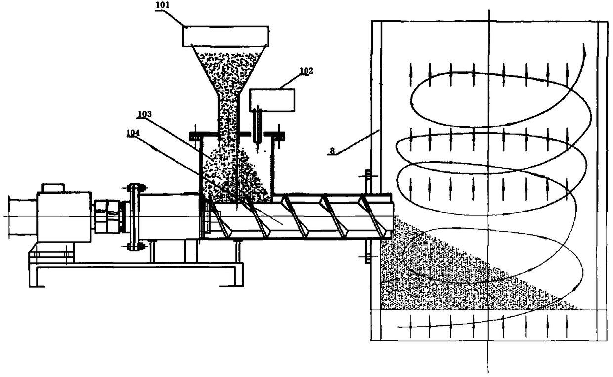
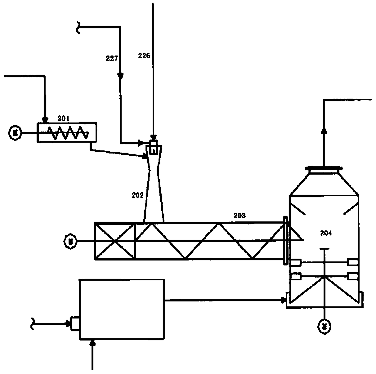
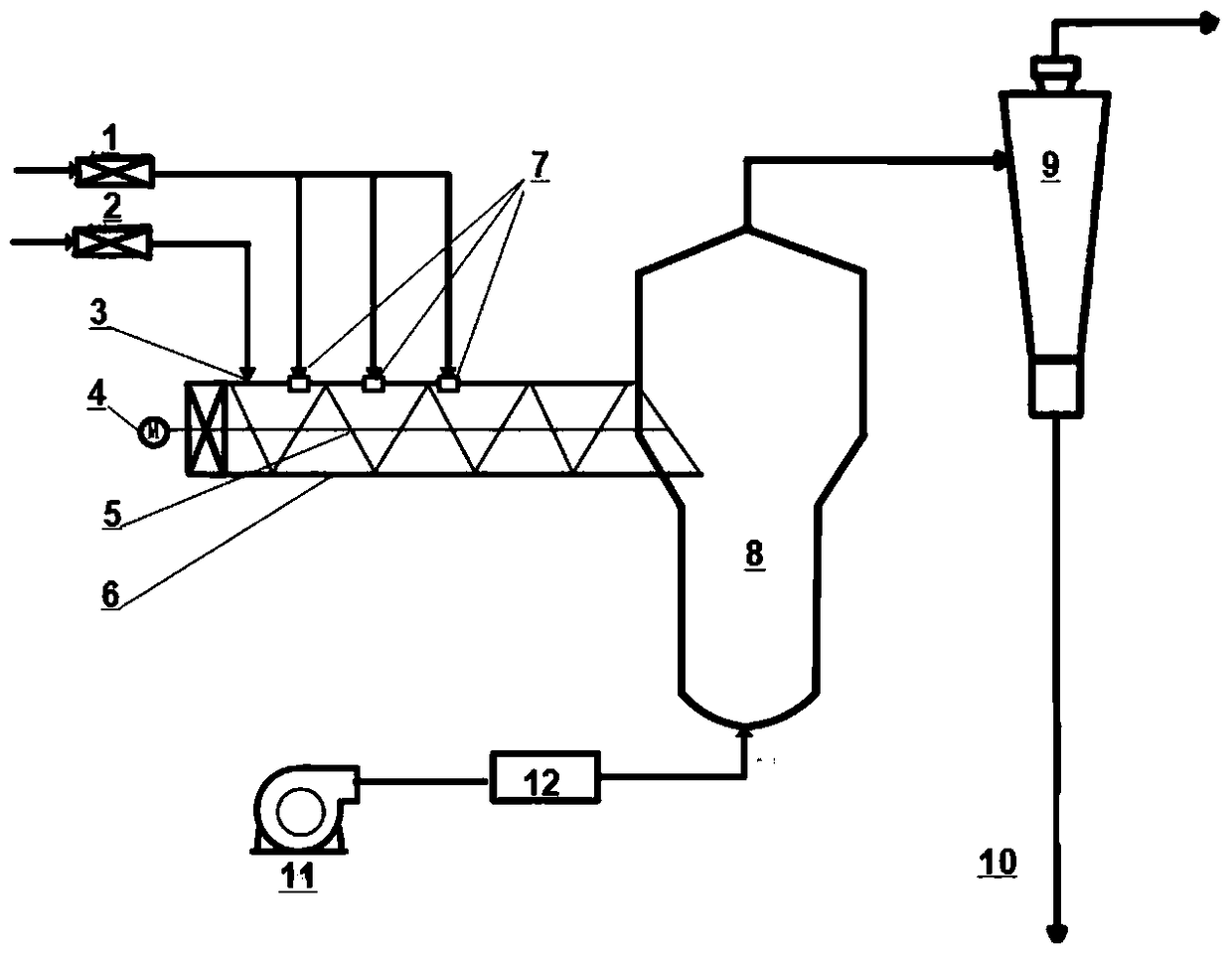
[0105] Figure 3 to Figure 8 A first preferred embodiment of the invention is shown. Figure 3 to Figure 8 The reference signs in include: impregnation liquid delivery system 1, particle carrier feeding system 2, particle carrier inlet 3, power system 4, transmission shaft 5, mixing conveyor 6, impregnation liquid nozzle 7, dryer 8, Separator 9 , impregnated carrier line 10 , conveyor belt 1125 , fan 1234 , air distribution plate 1235 .

[0106] Such as Figure 3 to Figure 8As shown, the impregnation equipment includes a particle carrier inlet, an immersion liquid nozzle, a mixing conveyor and a dryer, wherein the outlet of the mixing conveyor is connected to the dryer, and the particle carrier inlet is connected to the mixing conveyor The impregnating liquid nozzle is communicated with the mixing conveyor, and the impregnating liquid nozzle is located between the inlet of the particle carrier and the outlet of the mixing conveyor; the device also includes a Conveying devic...

Embodiment approach 1-1

[0117] The conveying device may be a transmission shaft (embodiment 1-1), a conveyor belt (embodiment 1-2) or a particle fluidization system (embodiment 1-3).

[0118] Embodiment 1-1:

[0119] The conveying device is a transmission shaft, and the transmission shaft is located in the mixing conveyor. The transmission shaft is driven by a power system including an electric motor. The transmission shaft in the mixer can be a threaded structure or a folded plate structure, preferably a folded plate structure. Preferably, the bottom of the mixing conveyor has a loose tuyere (not shown in the figure), which can reduce the wear and tear during the turning process of the particle carrier.

[0120] To facilitate delivery of the particulate carrier into the dryer, the mixing conveyor and the transfer shaft are sloped downward from the inlet of the particulate carrier to the outlet of the mixing conveyor. The inclination angle can be greater than 0 to 45°, preferably 10-30°.

Embodiment approach 1-2

[0122] The conveying device is a conveyor belt, and the conveyor belt is located in the mixing conveyor. The conveyor belt is driven by a power system including a motor. The conveyor belt is preferably mesh-shaped, that is, it is provided with a plurality of holes (not shown in the figure) as air outlets, which are used as loose air outlets for the carrier, and promote the uniform mixing of the carrier with the impregnating liquid during the transmission process. The conveying speed of the conveyor belt can be 0.5-8m / s, preferably 1-5m / s.


PUM

PropertyMeasurementUnit
particle sizeaaaaaaaaaa

Abstract

The invention discloses a particle carrier impregnation method. The method comprises steps as follows: (1) contacting impregnation liquid droplets with a particle carrier, wherein the contact time is shorter than 5 s; (2) drying the impregnated particle carrier. According to the method, an impregnation liquid is fully contacted with the particle carrier for a short time (shorter than 5 s) before drying, so that uniform distribution of active components during impregnation can be guaranteed, the particle size distribution and the strength of the impregnated carrier are also guaranteed, and a prepared adsorbent product has the good wear resistance in the reaction process.

Description

technical field [0001] The invention relates to an impregnation method, in particular to an impregnation method for particle carriers. Background technique [0002] Impregnation is a very important process step in many catalyst preparation processes. When a carrier with a porous structure is immersed in a solution containing an active component, the solution is sucked from the surface of the carrier into the pores of the carrier under the action of capillary force, and the active component as a solute penetrates and diffuses inward with the solution, and is then absorbed into the pores of the carrier. The active point on the surface of the carrier is adsorbed, or deposited or ion exchanged, or even reacted, and finally the active component is loaded on the carrier. [0003] Conventional impregnation methods mainly include supersaturated impregnation and saturated impregnation. Supersaturated impregnation includes intermittent impregnation and continuous impregnation, and c...

Claims


Application Information

Patent Timeline
Patent Type & Authority Patents(China)
IPC IPC(8): B01J37/02B01J20/32
Inventor 龙军田辉平林伟
Owner CHINA PETROLEUM & CHEM CORP
Why Eureka
Try Eureka