
Arrestor test rack

A test stand and arrester technology, which is applied to instruments, measuring devices, measuring electricity, etc., can solve the problems of low work efficiency and cumbersome operation of arrester test, and achieve the effect of reducing workload, improving test work efficiency, and simplifying steps.

Active Publication Date: 2013-11-13
STATE GRID CORP OF CHINA +1
View PDF6 Cites 8 Cited by
  • Summary
  • Abstract
  • Description
  • Claims
  • Application Information

AI Technical Summary

Problems solved by technology

[0003] The present invention provides a lightning arrester test frame, which overcomes the above-mentioned deficiencies in the prior art, and can effectively solve the problems of cumbersome test operation and low work efficiency of the existing lightning arrester

Method used


Image

  • Arrestor test rack

Examples


Embodiment Construction

[0017] The present invention is not limited by the following examples, and specific implementation methods can be determined according to the technical solutions of the present invention and actual conditions.

[0018] In the present invention, for the convenience of description, the description of the relative positional relationship of each component is based on the description attached to the description. figure 1 For example, the positional relationship of front, back, up, down, left, right, etc. is based on the attached figure 1 determined by the layout direction.

[0019] Below in conjunction with embodiment and accompanying drawing, the present invention will be further described:

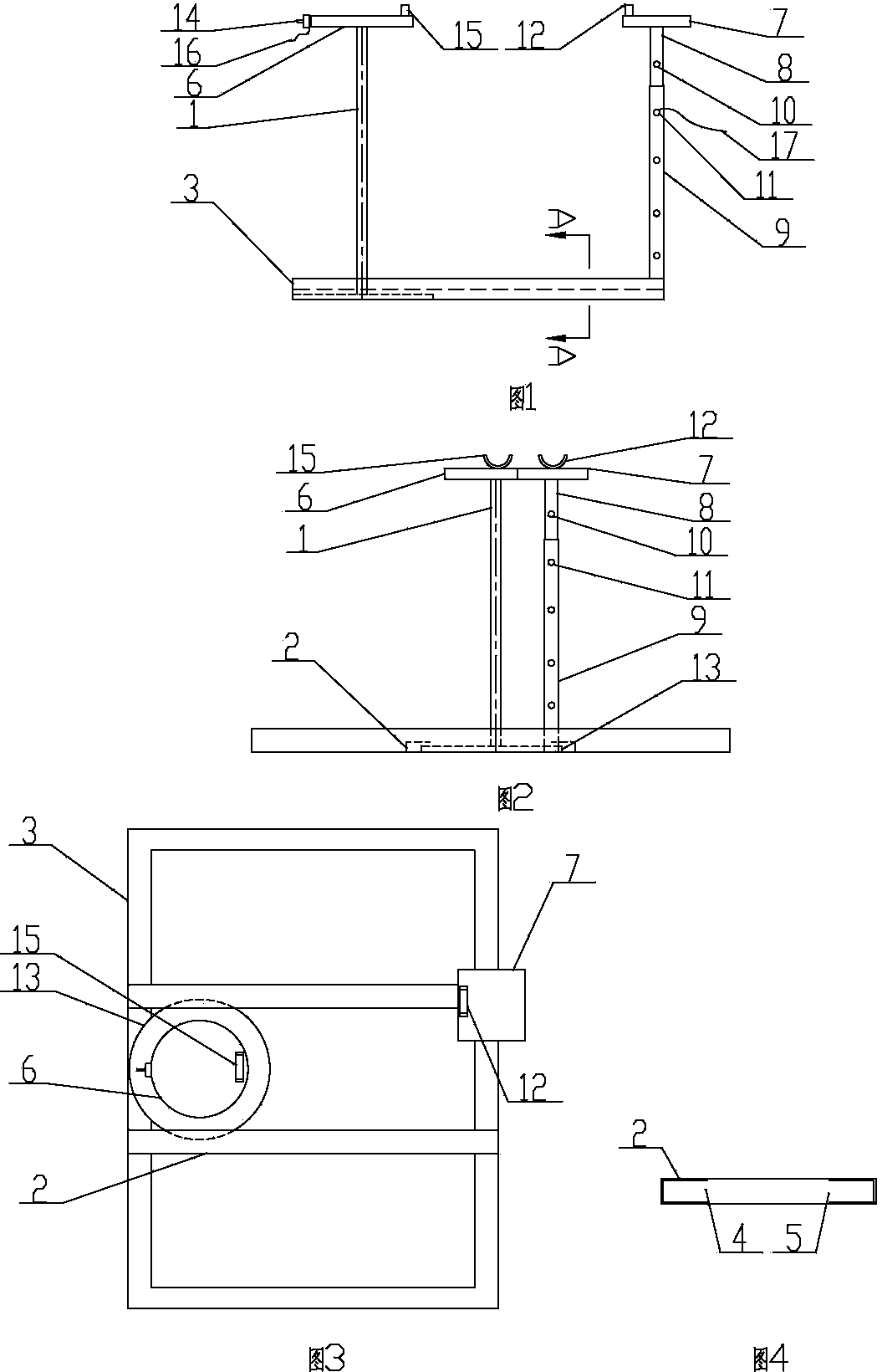
[0020] as attached Figures 1 to 4 As shown, the arrester test frame includes a left moving insulating rod 1, a right adjusting conductive rod and a rectangular frame 2, and the front side and the rear side of the rectangular frame 2 are respectively provided with a front chute ...


PUM


Abstract

The invention relates to the technical field of arrestor testing devices, in particular to an arrestor test rack. The arrestor test rack comprises a left moving insulating rod, a right adjusting conducting rod and a rectangular framework, wherein a front sliding chute and a rear sliding chute are formed in the front side and the rear side of the inside of the rectangular framework respectively, and openings of the front sliding chute and the rear sliding chute are opposite; a sliding plate is fixed at the lower end of the left moving insulating rod, is nested in the front sliding chute and the rear sliding chute and can move in the front sliding chute and the rear sliding chute; a left conducting supporting seat is fixed at the upper end of the left moving insulating rod, and a boosting wire is fixedly mounted on the left conducting supporting seat; and the right adjusting conducting rod is fixed at the right end of the rectangular framework, and a ground wire is fixedly mounted on the right adjusting conducting rod. The arrestor test rack is reasonable and compact in structure and convenient to use; during the arrestor testing process, when test of one arrestor is finished and another arrestor is tested, the ground wire and the boosting wire are not required to be repeatedly disassembled and assembled, so that the steps are simplified, the work efficiency of the test is improved, and the work load of a testing worker is reduced.

Description

technical field [0001] The invention relates to the technical field of lightning arrester test devices, and relates to a lightning arrester test frame. Background technique [0002] At present, the voltage of a large number of lightning arresters used is 10 kV to 35 kV. In order to prevent the lightning arrester from losing its lightning protection effect due to the failure of the lightning arrester, it is necessary to test the lightning arrester. During the test, it is necessary to install a grounding wire and a booster wire for each arrester. When it is necessary to continue testing another arrester after the test of one arrester is completed, the grounding wire and booster wire must be repeatedly disassembled. Therefore, there are problems of tedious operation and low work efficiency of the arrester test. Contents of the invention [0003] The invention provides a lightning arrester test frame, which overcomes the above-mentioned deficiencies in the prior art, and can ...

Claims


Application Information

Patent Timeline
Patent Type & Authority Applications(China)
IPC IPC(8): G01R1/04G01R31/00
Inventor 徐晓山郭良松徐波刘巨勇
Owner STATE GRID CORP OF CHINA
Learn More