Beam forming device based on sparse signals and method of device

A sparse signal and shaper technology, applied in the field of communication, can solve the problems of reducing sampling rate and sampling data volume, increasing signal bandwidth and working frequency band, high sampling rate and large data volume, etc., to achieve simple implementation and small sampling data volume Effect

Inactive Publication Date: 2013-11-13
XIDIAN UNIV
View PDF4 Cites 14 Cited by
  • Summary
  • Abstract
  • Description
  • Claims
  • Application Information

AI Technical Summary

Problems solved by technology

[0006] The purpose of the present invention is to overcome the deficiencies of the above-mentioned prior art, solve the problems of high sampling rate and large data volume due to the increase of signal bandwidth and operating frequency band in array radar, and propose a beamformer based on sparse signals, which reduces the sampling rate. Rate and amount of sampled data

Method used


Image

  • Beam forming device based on sparse signals and method of device
  • Beam forming device based on sparse signals and method of device
  • Beam forming device based on sparse signals and method of device

Examples


Embodiment Construction

[0031] The present invention will be described in detail below in conjunction with specific embodiments.

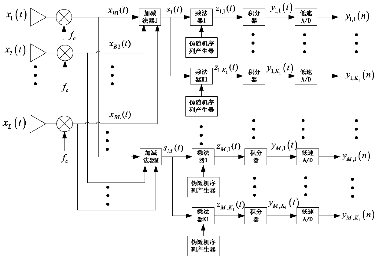
[0032] The beamformer based on the sparse signal of the present invention includes L array element receiving antennas, M multi-input analog adder-subtractors, M×K 1 Analog multipliers, M×K 1 A pseudo-random sequence generator, M×K 1 integrators and M×K 1 A low-speed A / D converter, each array element antenna in the L array element receiving antennas is connected with M multi-input analog adder-subtractors, each multi-input adder-subtractor and K 1 The analog multiplier is connected, the pseudo-random sequence generator is connected with the analog multiplier, the analog multiplier is connected with the integrator, and the integrator is connected with the A / D converter. In order to achieve the purpose of reducing the amount of data, it is required that L>M. In this embodiment, L is 32, M is 16, and K 1 for 10.

[0033] The beamforming process is described as follows: ...


PUM


Abstract

The invention discloses a beam forming device based on sparse signals and a method of the device. The beam forming device comprises an array element receiving antenna, a multi-input analog adder, an analog multiplier, a pseudorandom sequence generator, an integrator and an A/D convertor, wherein weight coefficients of the multi-input analog adder are submitted to random Bernoulli distribution. After sampling, data reconstruction steps are as follows: 1), main diagonal elements are taken, and sampling data of (K1+1)th row are constructed; 2), the main diagonal elements are taken, and sampling data of (K1+2)th row are constructed; 3); sampling data of left (K2-2) rows are constructed sequentially; and the data of all the rows are summed. According to the beam forming device and the method, a compressed sampling technology is adopted, so that broadband signals can be sampled at a low sampling rate; an airspace projection measurement matrix selects a random Bernoulli array, a phase shifter and a multiplier are not required; a multi-channel structure and a sampling data reconstruction manner are used during time-domain observation projection; and more sampling data comprising a large amount of information can be acquired by the aid of fewer channels.

Description

technical field [0001] The invention belongs to the technical field of communication, and further relates to a sparse signal-based beamformer and a method thereof in the technical field of array radar. The invention solves the problems of high sampling rate and large data volume caused by increasing signal bandwidth and working frequency band in the array radar, and can be used for array radar beam formation. Background technique [0002] With the complexity of the war environment and the development of electronic countermeasures, various current military needs have put forward higher and higher requirements for radar functions. In order to meet these increasingly high requirements, modern radar systems have to continuously explore and research in the time-frequency domain and air domain. On the one hand, they adopt large signal bandwidth and system operating frequency band; angular resolution, or increase the number of sensors to increase channel capacity. Under the frame...

Claims


Application Information

Patent Timeline
Patent Type & Authority Applications(China)
IPC IPC(8): G01S7/02
Inventor 王敏张作浩菅立龙章建成
Owner XIDIAN UNIV
Why Eureka
Try Eureka