
Space mouse and method for obtaining displacement of space mouse

A space mouse, displacement technology, applied in the field of mouse, can solve the problem of user's freedom of manipulation and other problems

Active Publication Date: 2013-11-13
SOUTH CHINA NORMAL UNIVERSITY
View PDF7 Cites 10 Cited by
  • Summary
  • Abstract
  • Description
  • Claims
  • Application Information

AI Technical Summary

Problems solved by technology

These micro-displacement measurement technologies used by traditional "desktop" mice need to keep a close distance with the reference object, so this kind of mouse cannot be used without "desktop", which limits the user's freedom of manipulation

Method used


Image

  • Space mouse and method for obtaining displacement of space mouse
  • Space mouse and method for obtaining displacement of space mouse
  • Space mouse and method for obtaining displacement of space mouse

Examples


Embodiment 1

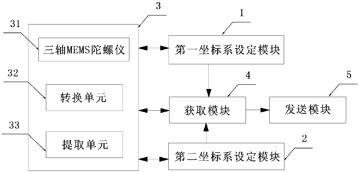
[0071] Such as figure 1 As shown, it is a structural block diagram of the space mouse described in this implementation. It includes a first coordinate system setting module 1 , a second coordinate system setting module 2 , a detection module 3 , an acquisition module 4 and a sending module 5 . The detection module 3 is connected to the first coordinate system setting module 1 , the second coordinate system setting module 2 , the acquiring module 4 and the sending module 5 respectively. The first coordinate system setting module 1 sets the first reference coordinate system of the space mouse on the display screen, and records its coordinates in the first reference coordinate system. The first reference coordinate system includes coordinate axes with the center point of the display screen as the origin, the length direction of the display screen as the horizontal axis, and the width direction as the vertical axis. The second coordinate system setting module 2 sets the second r...

Embodiment 2

[0109] Such as Figure 4 As shown, it is a structural block diagram of the space mouse described in this embodiment. It includes a first coordinate system setting module, a second coordinate system setting module, a detection module, an acquisition module and a sending module. The first coordinate system setting module, the second coordinate system setting module, the detection module and the sending module in this embodiment are the same as those in the first embodiment.

[0110] The difference between this embodiment and Embodiment 1 is that the acquiring module includes a three-axis accelerometer, a second converting unit, an integrating unit and a mapping unit. The three-axis accelerometer measures the acceleration of the three axes of the space mouse. The second conversion unit converts the three-axis acceleration to the acceleration corresponding to the three axes in the second reference coordinate system. The integrating unit integrates the speeds of the three axes o...


PUM


Abstract

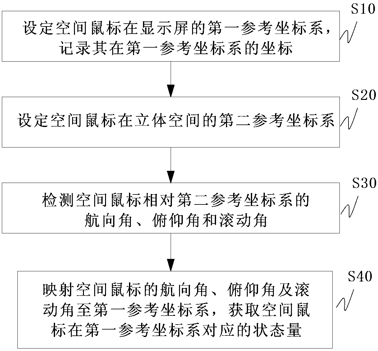
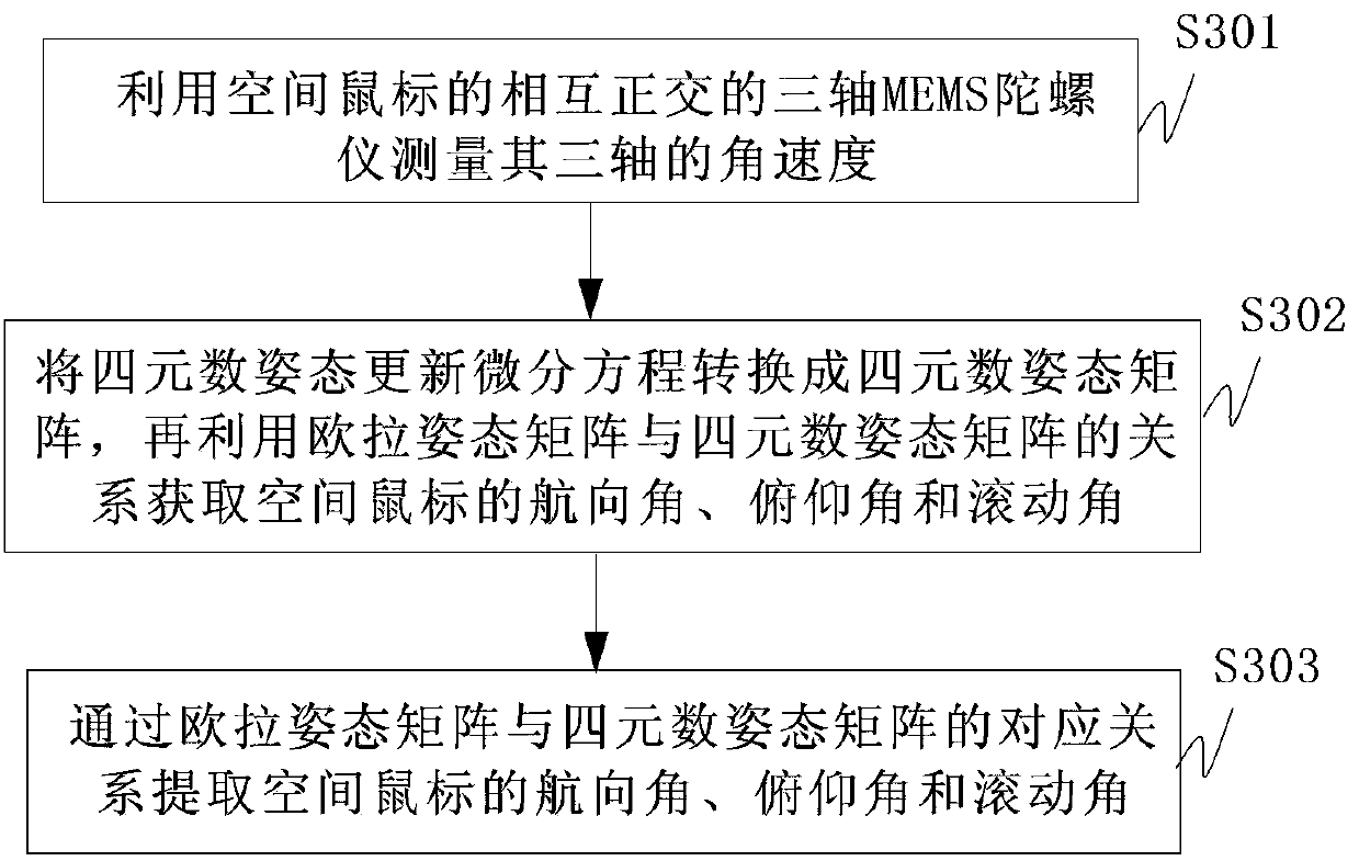
The invention discloses a method for obtaining the displacement of a space mouse. The method comprises the following steps of setting a first reference coordinate system of the space mouse on a display screen, and recording coordinates of the space mouse in the first reference coordinate system; setting a second reference coordinate system of the space mouse in a stereoscopic space; detecting a course angle, a pitch angle and a roll angle, which are relative to the second reference coordinate system, of the space mouse; mapping the course angle, the pitch angle and the roll angle of the space mouse to the first reference coordinate system, and obtaining corresponding state quantities of the space mouse in the first reference coordinate system; and sending the state quantities of the space mouse in the first coordinate system to a host computer in real time. According to the method disclosed by the invention, by combining the space mouse with a navigation posture theory, the displacement of the space mouse can be detected and mapped to the display screen, and thus the function of an existing mouse can also be realized by the space mouse without depending on a reflection platform.

Description

technical field [0001] The invention relates to a mouse, in particular to a space mouse which does not need a desktop platform as a light reflector and a method for obtaining the displacement of the space mouse. Background technique [0002] Mouse, as a very important input device, brings great convenience to our work and life. The development of the mouse, from mechanical mouse to optical mouse, from wired to wireless, from single function to multi-function, makes user operation more and more convenient, and human-computer interaction is getting higher and higher. The principle of traditional "desktop" mouse, including mechanical mouse and optical mouse, is to use micro-displacement measurement technology to measure the displacement of the mouse on the X-axis and Y-axis relative to the platform below it (usually refers to the desktop, mouse pad) . By continuously and quickly obtaining the displacement of the mouse in the XY two directions in each small time interval, the ...

Claims


Application Information

Patent Timeline
IPC IPC(8): G06F3/0346G01B21/04
Inventor 林志豪陈文创唐小煜李志为钟清华
Owner SOUTH CHINA NORMAL UNIVERSITY
Learn More