
Power detection control device and power supply control system

A control device and power detection technology, applied in the electronic field, can solve the problems of electronic equipment system failure, poor circuit performance, large power consumption, etc., and achieve the effect of preventing burning

Active Publication Date: 2016-02-10
GCI SCI & TECH
View PDF3 Cites 0 Cited by
  • Summary
  • Abstract
  • Description
  • Claims
  • Application Information

AI Technical Summary

Problems solved by technology

[0003] When testing or using an electronic device, it needs to supply power to the electronic device. Some high-performance and high-frequency electronic devices usually need to provide multiple different operating voltages, such as high-definition (High Definition) set-top boxes, and these electronic products usually The power consumption is large, especially in the process of product testing, the requirements for the power supply are very strict, if the power supply sequence of the electronic equipment cannot meet the actual requirements, or the output voltage of the power supply does not meet the specifications, such as reverse connection of the power supply , load overload, poor circuit performance, etc., will cause these electronic equipment or devices to fail and stop working, and even burn the electronic devices and circuits on the main board of the internal circuit, such as chips, etc.

Method used


Image

  • Power detection control device and power supply control system
  • Power detection control device and power supply control system
  • Power detection control device and power supply control system

Examples


Embodiment Construction

[0039] The following will clearly and completely describe the technical solutions in the embodiments of the present invention with reference to the drawings in the embodiments of the present invention.

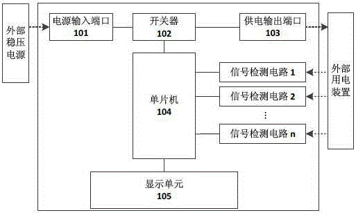
[0040] see figure 1 , is a schematic structural diagram of the first embodiment of a power detection control device provided by the present invention.

[0041] In this embodiment, the power detection control device includes: a power input port 101, a switch 102, a power supply output port 103, a single-chip microcomputer 104, a multi-channel signal detection circuit (such as figure 1 Signal detection circuit 1 shown in , signal detection circuit 2 , . . . , signal detection circuit n, where n≥2) and display unit 105 .

[0042] The power input port 101 is used to receive an external regulated power supply signal.

[0043] The power supply output port 103 is used to connect to an external electrical device, and when the switch 102 is in a conducting state, it is connected to t...


PUM


Abstract

The invention discloses a power source detection control device which comprises a power source input port, a power supply output port, a signal detection circuit, a singlechip and a display unit, wherein the power source input port is used for accessing an external voltage-stabilized power source signal; the power supply output port is used for being connected with an external power utilization device, is in a conducting state at a switch, accesses the external voltage-stabilized power source signal, and supplies power to the external power utilization device; the signal detection circuit is used for accessing a to-be-detected signal of the external power utilization device; the singlechip is used for judging whether the to-be-detected signal of the external power utilization device is normal, and when the to-be-detected signal is normal, the switch is controlled to be connected; when the to-be-detected signal is abnormal, the switch is controlled to be disconnected; and the display unit is used for outputting and displaying a result of detection performed by the singlechip on the external utilization device. The invention further provides a power supply control system, real-time monitoring of a working state of the power utilization device is realized, the system can supply power to the power utilization device according to the detection result, and flexible power supply protection can be performed on the power utilization device.

Description

technical field [0001] The invention relates to the field of electronic technology, in particular to a power detection control device and a power supply control system. Background technique [0002] Today, with the rapid development of electronic technology, people's daily life and work are inseparable from various electronic products. With the development of integrated electronic circuits and the improvement of process technology (such as the fineness of integrated circuits, production technology, etc.), the integration of various electronic products and equipment is getting higher and higher, and their functions are becoming more and more abundant. In the production process of various electronic products and equipment, it is necessary to test the circuit board circuit, and only after passing the test can it be put into the market for sale and use. [0003] When testing or using an electronic device, it needs to supply power to the electronic device. Some high-performance ...

Claims


Application Information

Patent Timeline
Patent Type & Authority Patents(China)
IPC IPC(8): H02H7/20
Inventor 张力余晓杰柯彬龙
Owner GCI SCI & TECH
Learn More