
Intelligent communication and power supply system and method based on MCU control module

A technology of control module and power supply system, applied in the field of intelligent communication and power supply system, can solve problems such as equipment and power supply cabinet loss, and achieve the effect of intelligent power supply

Active Publication Date: 2020-07-31
钱才英
View PDF12 Cites 0 Cited by
  • Summary
  • Abstract
  • Description
  • Claims
  • Application Information

AI Technical Summary

Problems solved by technology

[0004] At present, when the power supply cabinet supplies power to the equipment, it usually supplies power uniformly, and directly supplies power to the equipment that does not need to be operated or has sufficient power, which will cause the equipment that does not need to be powered to be powered for a long time, causing equipment and The loss of the power supply cabinet, this application aims to analyze the power of different devices connected to the power supply cabinet one by one, supply power to the directionality of the equipment that needs power supply, and realize the intelligent power supply of the power supply cabinet

Method used


Image

  • Intelligent communication and power supply system and method based on MCU control module
  • Intelligent communication and power supply system and method based on MCU control module
  • Intelligent communication and power supply system and method based on MCU control module

Examples


Embodiment 1

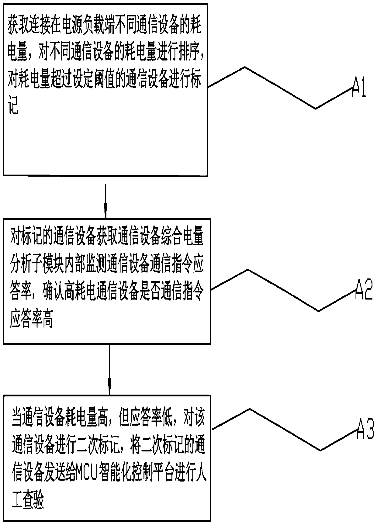
[0063] Embodiment 1: Limiting conditions, the remaining power of different communication equipment is set by the comprehensive power analysis sub-module of the communication equipment to be 2.5kwh, 1.1kwh, 3.2kwh, 0.3kwh, wherein the set threshold is 0.5kwh, and the monitoring 0.3kwh is less than the set Set the threshold to 0.5 kwh, directly send the power of the communication device to the low battery marking sub-module, and the low battery marking sub-module marks the communication device and gives priority to charging;

[0064] Among them, the monitored 2.5kwh, 1.1kwh, and 3.2kwh are greater than the set threshold, and the response rates of different communication equipment to externally connected communication equipment are monitored to be 0.3, 0.7, and 0.51, and the comprehensive power value of different communication equipment is set to C. formula:

[0065] C1=2.5*(1- 0.3)=1.75; C2=1.1*(1- 0.7)=0.33; C3=3.2*(1- 0.51)=1.56; calculated, the comprehensive power value of di...

Embodiment 2

[0066] Embodiment 2: limited conditions, the communication equipment comprehensive power analysis sub-module sets the remaining power of different communication equipment as 4.5 kwh, 1.4 kwh, wherein the set threshold is 0.5 kwh, wherein the monitored 4.5 kwh, 1.4 kwh is greater than the set Threshold, monitor the response rate of communication commands of different communication devices to externally connected communication devices to 0.9, 0.2, set the comprehensive power value of different communication devices to C, according to the formula:

[0067] C1=4.5*(1-0.9)=0.45; C2=1.4*(1-0.2)=1.12; calculated, the comprehensive power value of different communication devices, sort the comprehensive power values ​​of different communication devices, and form a list , sent to the low-battery marking sub-module, the low-battery marking sub-module marks the communication devices with low comprehensive power in the list, and sends the marking results to the intelligent management module ...

Embodiment 3

[0068] Embodiment 3: Limiting conditions, setting the current monitoring value of the main supply cable in the communication device A to 12A, the current monitoring of the slave power supply cable is 1A, 1.7A, 2A, the current power supply load terminal voltage value is 220V, and the power factor is set to 0.9, set the load power of communication equipment A as P, according to the formula:

[0069] P=220*(12A+1A+1.7A+2A)*0.9=3306.6W

[0070] The calculated load power of the current communication device A is 3306.6W. Calculate the load power of different communication devices one by one through the above calculation formula and record them. When the load power of different communication devices is monitored within the set threshold, the set threshold is greater than 1100W. Different communication devices output suitable current and voltage within the adaptable range to supply power. When the load power of different communication devices is not within the set threshold, the load ...


PUM


Abstract

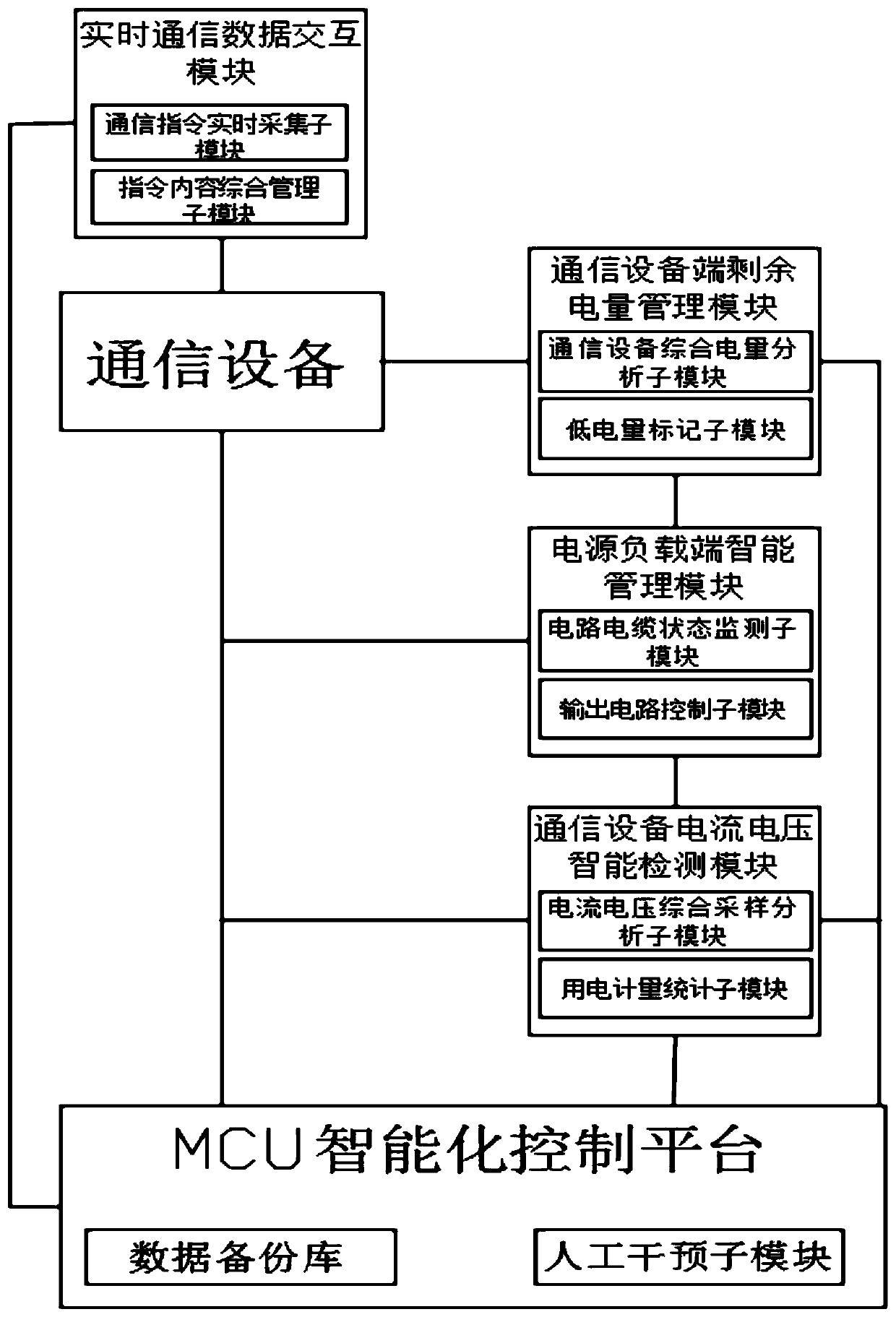
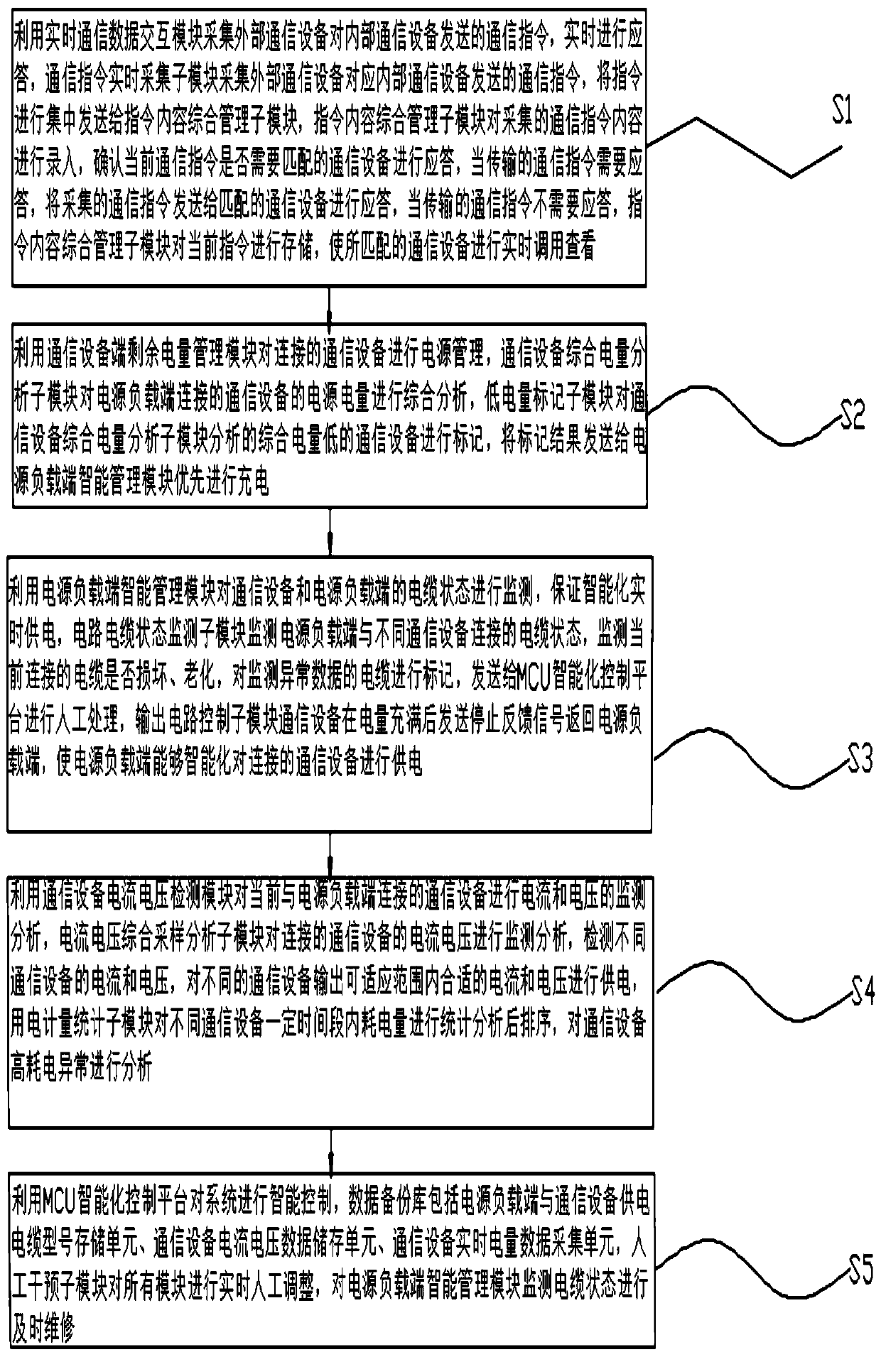
The invention discloses an intelligent communication and power supply system and method based on an MCU control module. The system comprises a communication device, a real-time communication data interaction module, a communication device end residual electric quantity management module, a power supply load end intelligent management module, a communication device current and voltage detection module and an MCU intelligent control platform. The real-time communication data interaction module is used for collecting a communication instruction sent by an external communication device to an internal communication device. The communication equipment end residual electric quantity management module is used for carrying out power supply management on connected communication equipment; the powersupply load end intelligent management module is used for monitoring cable states of the communication equipment and the power supply load end; wherein the communication equipment current and voltagedetection module is used for monitoring and analyzing current and voltage of communication equipment currently connected with a power supply load end, and the MCU intelligent control platform is usedfor intelligently controlling the system and aims to analyze the electric quantity of different equipment connected to the power supply cabinet one by one so as to realize intelligent power supply ofthe power supply cabinet.

Description

technical field [0001] The invention relates to the field of MCU control, in particular to an intelligent communication and power supply system and method based on an MCU control module. Background technique [0002] The micro-control unit is called a single-chip microcomputer or a single-chip microcomputer, which appropriately reduces the frequency and specifications of the central processing unit, and integrates peripheral interfaces such as memory, counter, USB, A / D conversion, UART, PLC, DMA, and even LCD drive circuits. All are integrated on a single chip to form a chip-level computer, which can be controlled in different combinations for different applications. Such as mobile phones, PC peripherals, remote controls, automotive electronics, industrial stepping motors, control of robot arms, etc., can all be seen in MCU. [0003] Single-chip microcomputers can be divided into general-purpose and special-purpose according to the scope of application. The dedicated type ...

Claims


Application Information

Patent Timeline
Patent Type & Authority Applications(China)
IPC IPC(8): H02J13/00H02J7/00G01R31/08G01R19/165G05B19/042
CPCG01R19/16538G01R31/083G05B19/042H02J7/00032H02J7/0048H02J13/00002Y04S10/40
Inventor 蒋知秋
Owner 钱才英
Learn More